Double Tube Sheet Heat Exchangers in Biopharma: Technical guide

Why Double Tube Sheet heat exchangers are essential in biopharmaceutical processes

Double Tube Sheet (DTS) heat exchangers are an engineering solution widely used in the biotechnological and biopharmaceutical industries. Their specialized Double Tube Sheet design provides an extra safety barrier that prevents cross-contamination between fluids, meeting the stringent sanitary requirements of processes such as vaccine production, cell bioprocessing, and injectable drug manufacturing. Below is a comprehensive technical guide on these devices, intended for professionals in the sector.

1. Technical definition of the double tube sheet exchanger

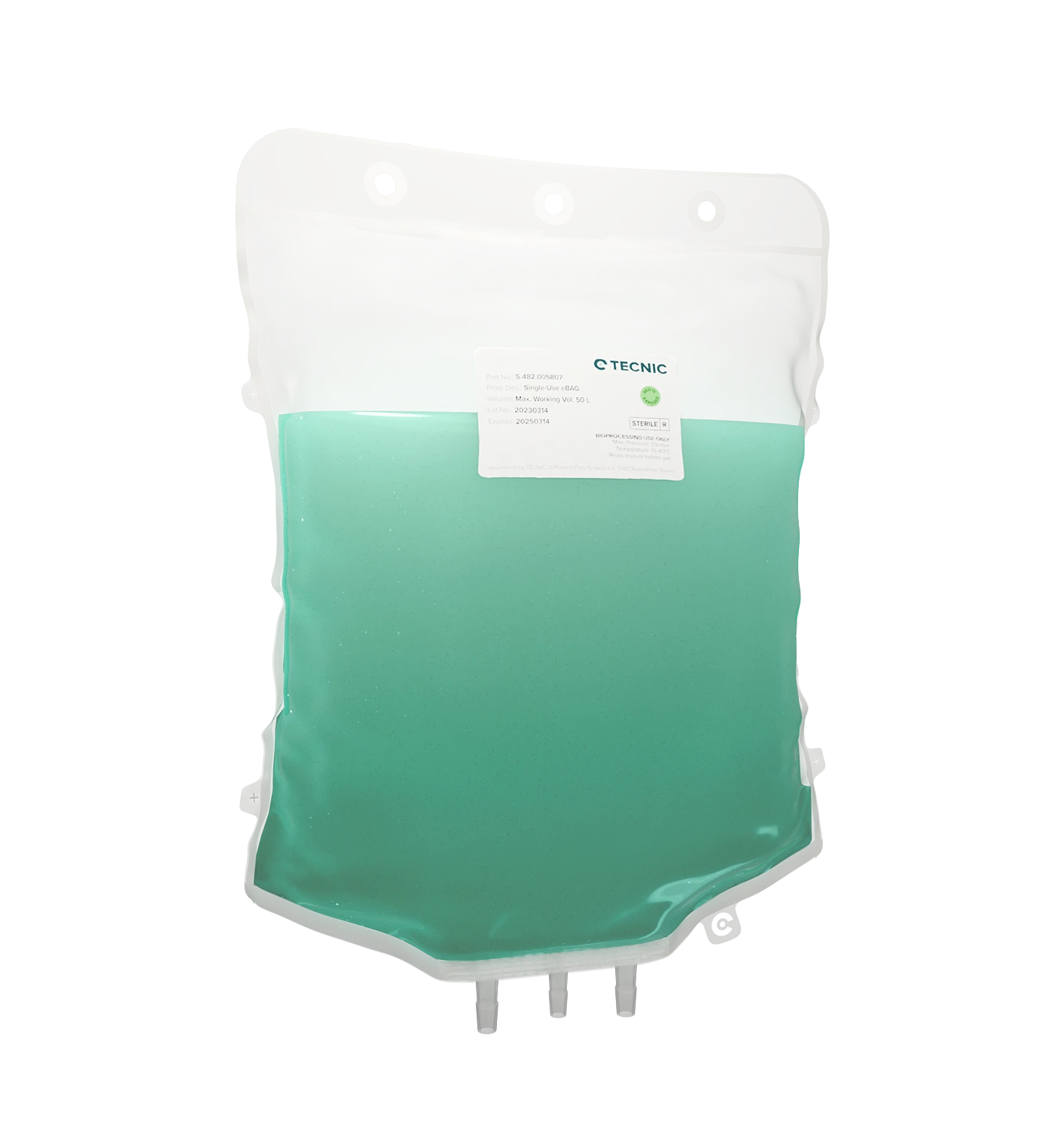
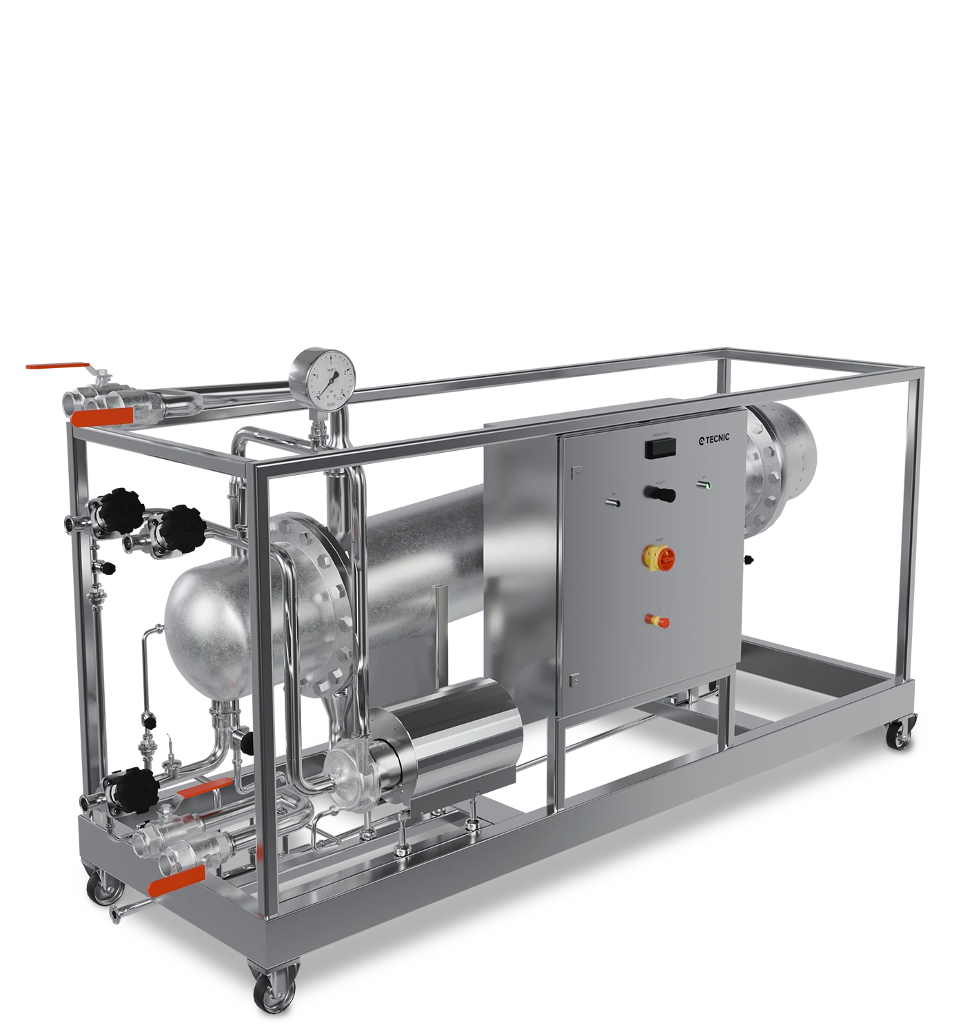
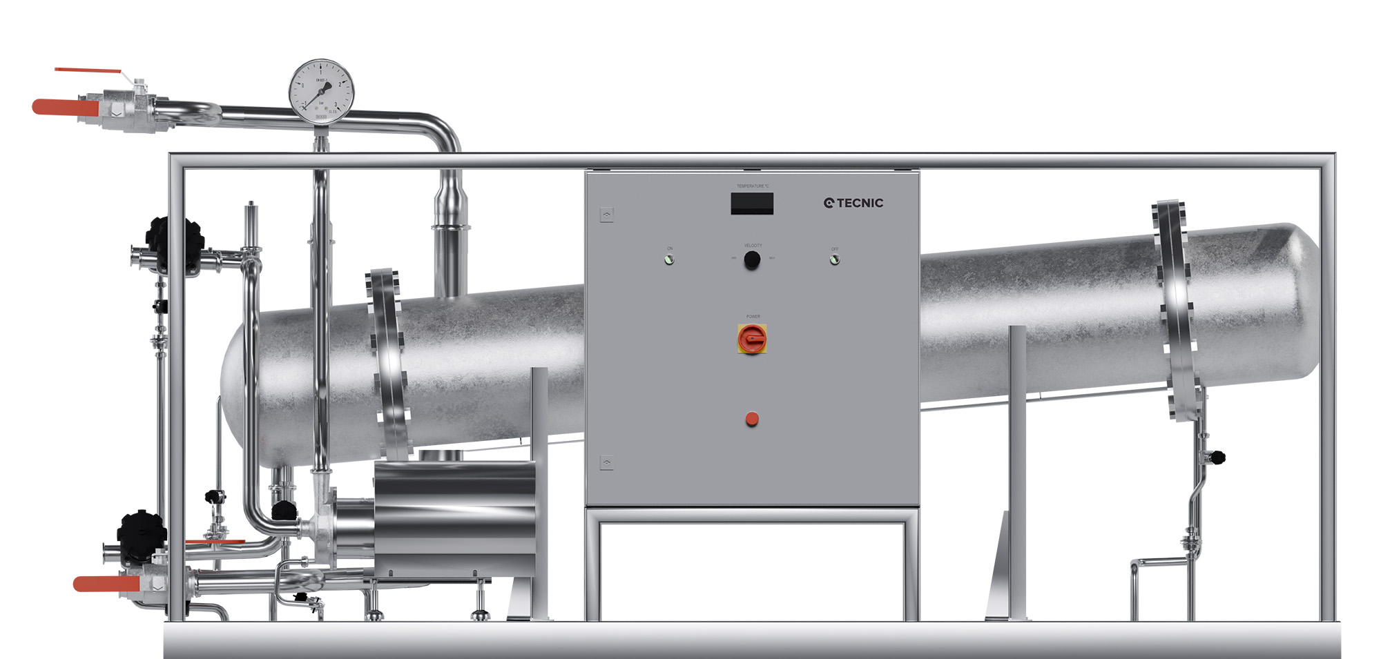
A Double Tube Sheet heat exchanger is a type of shell-and-tube heat exchanger that incorporates two parallel tube sheets at each end of the tube bundle, separated by a small gap or chamber. Each tube runs through both sheets and is fixed (by mechanical expansion and/or welding) to each one, creating a double sealing barrier at the tube-to-sheet joint. This design ensures that if a leak occurs in any tube or in its joint with the tube sheet, the fluids will not mix: the leaking fluid will remain confined within the space between the two tube sheets instead of entering the opposite circuit. In other words, any leakage will emerge into the intermediate chamber (usually open to the atmosphere) where it can be quickly detected, avoiding contamination of the fluid on the other side.

From a construction standpoint, the tube sheets (also known as tube plates) are perforated metal discs where the ends of the tubes are fixed. In the double-sheet design, two separate plates are used at each end: one connected to the head side (product) and the other to the shell side (utility). The space between the plates is usually vented or constantly drained to serve as a leakage detection zone. In this way, the DTS exchanger provides extra protection against leaks compared to a traditional single-tube-sheet design, by adding a second barrier and a relief zone where any fault can be identified before becoming a problem.

2. Detailed operating principle

In terms of heat transfer, a Double Tube Sheet heat exchanger operates under the same thermodynamic principles as a conventional shell-and-tube exchanger: typically, two fluids (product and utility) flow through separate paths (one inside the tubes and the other in the shell annulus), exchanging heat through the tube wall. Countercurrent flow is often used to maximize thermal efficiency. The DTS design stands out in how it handles a potential leak:

  • Controlled leakage path: If a tube cracks or develops a pinhole, or if the joint between the tube and the internal sheet fails, the fluid would escape through the breach but would not enter the opposite circuit. Thanks to the double-sheet design, the fluid exits through the intermediate area (usually visible via an inspection or drainage port) rather than contaminating the fluid on the other side. For example, in a conventional water-to-water exchanger, a tube rupture might allow low-purity water to mix with high-purity water. In contrast, with a DTS design, the water would escape between the sheets and be immediately detected as an external leak, triggering alarms or inspections without any direct contact between both water streams.
  • Early leak detection: The space between the two tube sheets is open to the atmosphere or connected to a detection system, so any leak creates a visible or measurable indication. It’s common to include a drain or a telltale port in this intermediate chamber, and even sensors (e.g., conductivity or liquid presence detectors) to alert the control system to an incipient leak. This allows maintenance personnel to respond quickly and repair the unit before cross-contamination occurs.
  • Thermal and mechanical integrity: The addition of a second tube sheet also improves the mechanical integrity of the exchanger. Since a single sheet is not shared by both sides, mechanical and thermal stress at the joints is reduced during operation. The small gap between the sheets can partially absorb thermal expansion differences between the tubes and the shell, minimizing the risk of thermal fatigue cracks. Additionally, tubes are typically fixed to both sheets by hydraulic expansion or rolling, and often with seal welding on the outer sheet to ensure total tightness. These welds follow sanitary standards (e.g., ASME BPE) and are smoothly polished to eliminate pores or cracks where contaminants could accumulate.

In summary, a Double Tube Sheet exchanger delivers efficient heat transfer while ensuring complete fluid separation. Any internal leak is quickly isolated and signaled before causing contamination. For this reason, this design is considered fail-safe for applications where purity and containment are essential, such as in high-demand biopharmaceutical processes.

3. Applications in the biotech and biopharma industry

Double Tube Sheet heat exchangers are most commonly used in sectors where product integrity and contamination prevention are critical. In biotechnology and biopharmaceuticals, they are typically used in:

  • High-purity water systems: They are ideal for Water for Injection (WFI) and Purified Water (PW) services, both in their generation stages and distribution loops. For example, WFI storage tanks often use DTS exchangers to keep the water circulating hot or to cool it before points of use, ensuring that the injectable water is never compromised by the utility fluid (typically industrial steam, cooling water, or another thermal medium).
  • Pure steam generation and pharmaceutical distillation: In WFI distillers and clean steam generators, using an evaporator or condenser with a Double Tube Sheet design is practically standard. This ensures that the heating industrial steam never mixes with the purified water or produced distillate. For example, multi-effect distillers often include DTS exchangers in each effect to isolate the motive steam from the sterile water. Likewise, in final clean steam condensers, a Double Tube Sheet prevents the cold (non-sterile) water from contaminating the pure steam condensate.
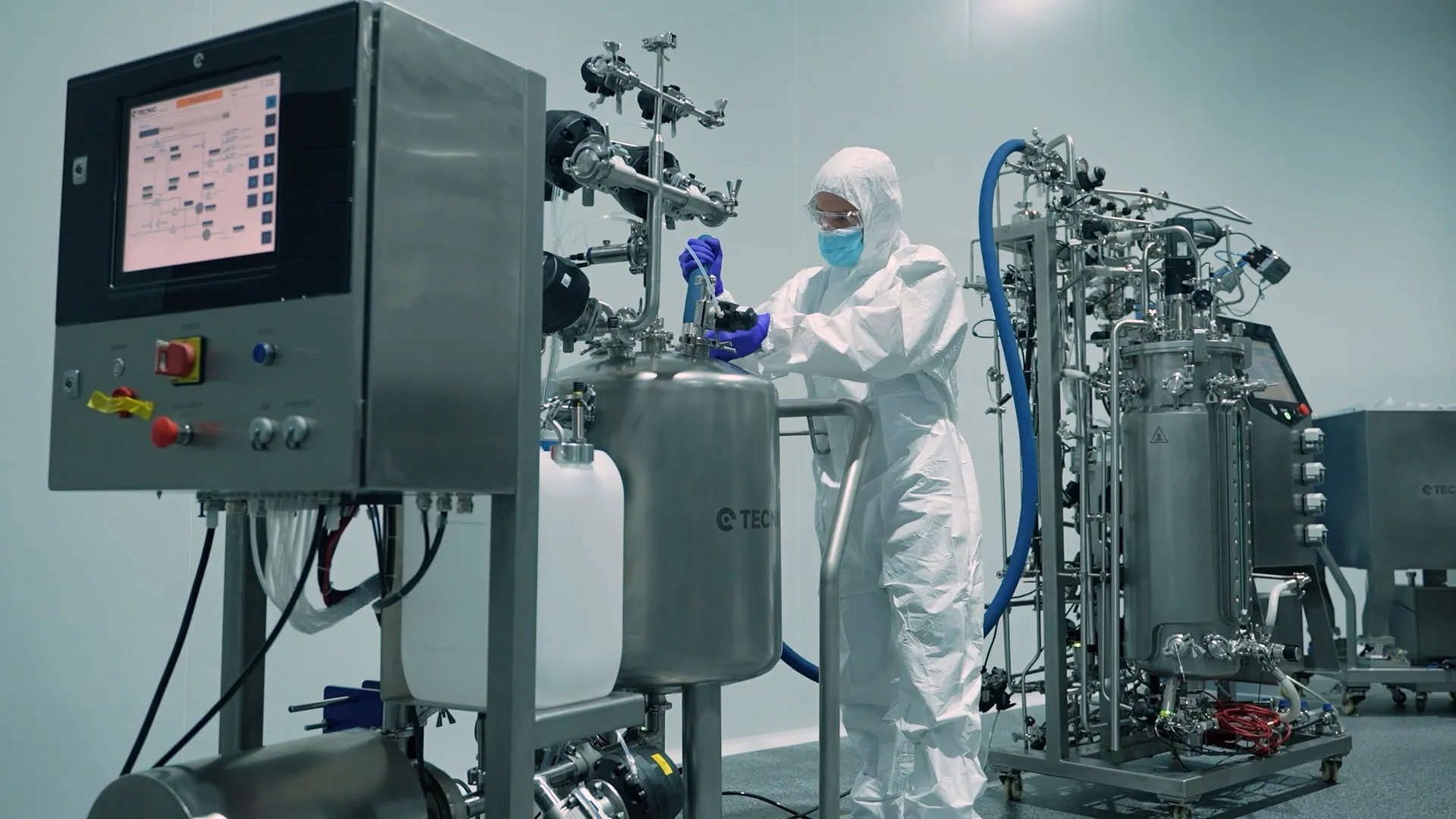
  • Heating/cooling loops in aseptic processes: Double Tube Sheet exchangers are commonly implemented in the thermal circuits of bioreactors, fermenters, and aseptic tanks, where a utility fluid (hot/cold water, glycol, clean steam, etc.) controls the temperature of the culture or product. With the DTS design, it’s guaranteed that the utility fluid (which may contain additives or lack sterility) will not enter the bioreactor even in the event of a failure, protecting the cell culture or biological solution. Many pharmaceutical plants install these exchangers in their thermal control systems specifically to avoid cross-contamination during fermentation or cell cultivation.
  • Formulation and sterile finish processes: In vaccine, injectable drug, and recombinant protein production, there’s often a need to heat or cool product solutions indirectly. A typical case is the rapid cooling of sterile solutions after sterilization (e.g., cooling a sterile saline solution before vial filling). Here, a conventional shell-and-tube exchanger would risk having the cooling fluid (e.g., tower water or glycol) contaminate the sterile solution in case of a leak. For this reason, Double Tube Sheet designs or equivalent alternatives are used to ensure that the pharmaceutical product never comes into contact with the cooling medium. GMP standards may even require this type of design in certain applications; for example, FDA guidelines for large-volume parenterals indicate that if a welded concentric double-tube or Double Tube Sheet exchanger is not used, a pressure differential with alarms must be maintained to prevent undetected leaks, demonstrating the regulatory preference for DTS designs in such cases.
  • Clean-in-Place (CIP) and Sterilization-in-Place (SIP): CIP systems that recirculate hot detergent solutions to clean process equipment sometimes use heat exchangers to heat those solutions. In critical applications, these exchangers may also be of the Double Tube Sheet type, preventing the cleaning solution (which may contain aggressive chemicals) from mixing with the heating medium. Likewise, some SIP systems (in-situ steam sterilization) incorporate DTS exchangers to generate pure steam from industrial steam, thus protecting the quality of the sterile steam.

In summary, typical applications cover any scenario where mixing two fluids of different qualities must be absolutely avoided. This includes pharmaceutical water loops (PW/WFI) in biopharma plants, media and buffer preparation units, aseptic production equipment for vaccines and biologics, and even high-end food applications (e.g., pasteurization of sensitive products). Their use has become standard in facilities where the purity of the product-side fluid is critical, providing peace of mind for engineers and compliance for regulatory audits.

4. Advantages compared to other types of heat exchangers

  • Cross-contamination prevention: The primary reason for using a DTS design is to prevent fluid mixing in the event of an internal leak. Unlike a traditional single-tube-sheet shell-and-tube exchanger, where a perforation in a tube can go unnoticed and contaminate the product, the Double Tube Sheet design inherently eliminates the risk of cross-contamination. This feature is crucial in industries where fluid mixing could lead to severe consequences (production batch loss, patient risk, etc.). Even compared to gasketed plate exchangers, DTS offers greater safety, since in plate systems a deteriorated gasket or cracked plate could allow undetected fluid crossover. In contrast, DTS provides a dual physical barrier and a visible leak point, practically eliminating the chance of unnoticed contamination.
  • Instant leak detection: Double Tube Sheet exchangers act as an "early warning" system in the event of failure. Any leak exits externally through the inter-sheet space, where it can be visually identified or quickly detected. In other designs, additional instrumentation (e.g., continuous differential pressure or conductivity monitoring) is needed to infer a possible internal leak. With DTS, the construction itself serves as passive detection. This simplifies safety protocols: many facilities rely on regular visual inspection of the port between sheets or a basic sensor in that chamber, which is more straightforward and reliable than interpreting pressure differences between flows. Thus, if a failure occurs, it’s immediately known and addressed before the process is compromised.
  • Compliance with regulations and GMP: The Double Tube Sheet configuration helps companies comply with the strictest regulatory standards. Agencies such as the FDA, EMA, and standards like ASME BPE recognize the benefits of this design. For instance, the FDA lists it as an acceptable design without additional measures in Water for Injection systems. Many GMP audits expect to see this type of exchanger at critical points. By choosing DTS, quality and engineering departments ensure their equipment is aligned with best industrial practices, avoiding observations related to potential cross-contamination. Furthermore, the design simplifies qualification: during the validation stage, it’s easier to justify that the contamination risk is virtually null thanks to the double sheet (reducing the need to demonstrate additional risk control measures).
  • Ease of maintenance and inspection: Although a two-sheet exchanger might initially seem more complex, it actually simplifies maintenance. Immediate leak detection means the equipment is rarely operated with hidden defects; the affected tube or joint is repaired as soon as the leak is identified, preventing larger damage or extended contamination. Also, many sanitary DTS designs allow easy access to the tube bundle by simply disassembling the heads, making cleaning and inspection of the product side straightforward. Unlike plate exchangers, which require disassembly of an entire plate pack and replacement of dozens of gaskets for thorough inspection, a Double Tube Sheet shell & tube requires removing just a few head bolts to visually inspect the tubes and internal sheet. The absence of numerous gaskets also reduces maintenance consumables. DTS systems are CIP/SIP compatible, allowing cleaning without disassembly, which streamlines preventive maintenance routines.
  • Other technical benefits: Double Tube Sheet exchangers may also incorporate other hygienic design advantages. For example, many pharmaceutical models use U-tubes to absorb thermal expansion, reducing mechanical stress, and allow complete drainage in both circuits, avoiding dead legs where liquids could stagnate. These units offer thermal performance comparable to any well-designed tubular exchanger, so adding the double sheet does not compromise heat transfer efficiency, it simply adds safety. In short, it offers the best of both worlds: high thermal efficiency and maximum sanitary safety.

It’s worth noting that the main disadvantage of DTS exchangers compared to simpler options is the higher initial cost and slight increase in manufacturing complexity. However, in the biopharmaceutical context, these costs are easily justified by the savings in contamination risk, product recalls, and regulatory compliance. Compared to the alternative of installing differential pressure monitoring systems or duplicating equipment, the Double Tube Sheet design is often the most robust and reliable long-term solution for avoiding cross-contamination.

5. Conclusion

The Double Tube Sheet (DTS) heat exchanger represents an essential solution in environments where product integrity is critical, as in biotechnological and pharmaceutical processes. Its Double Tube Sheet design ensures physical separation between fluids, immediately detects any leakage, and significantly reduces the risk of cross-contamination. These features make it a highly valued piece of equipment for Water for Injection production, cell cultivation, sterile formulations, and thermal loops in bioreactors.

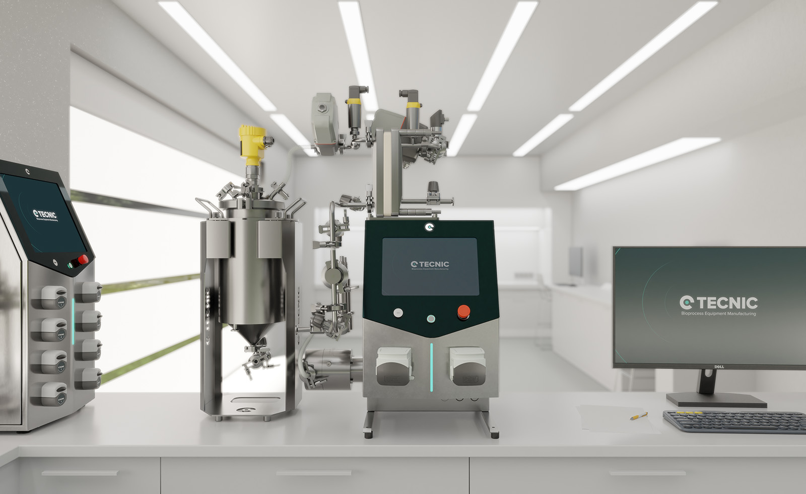
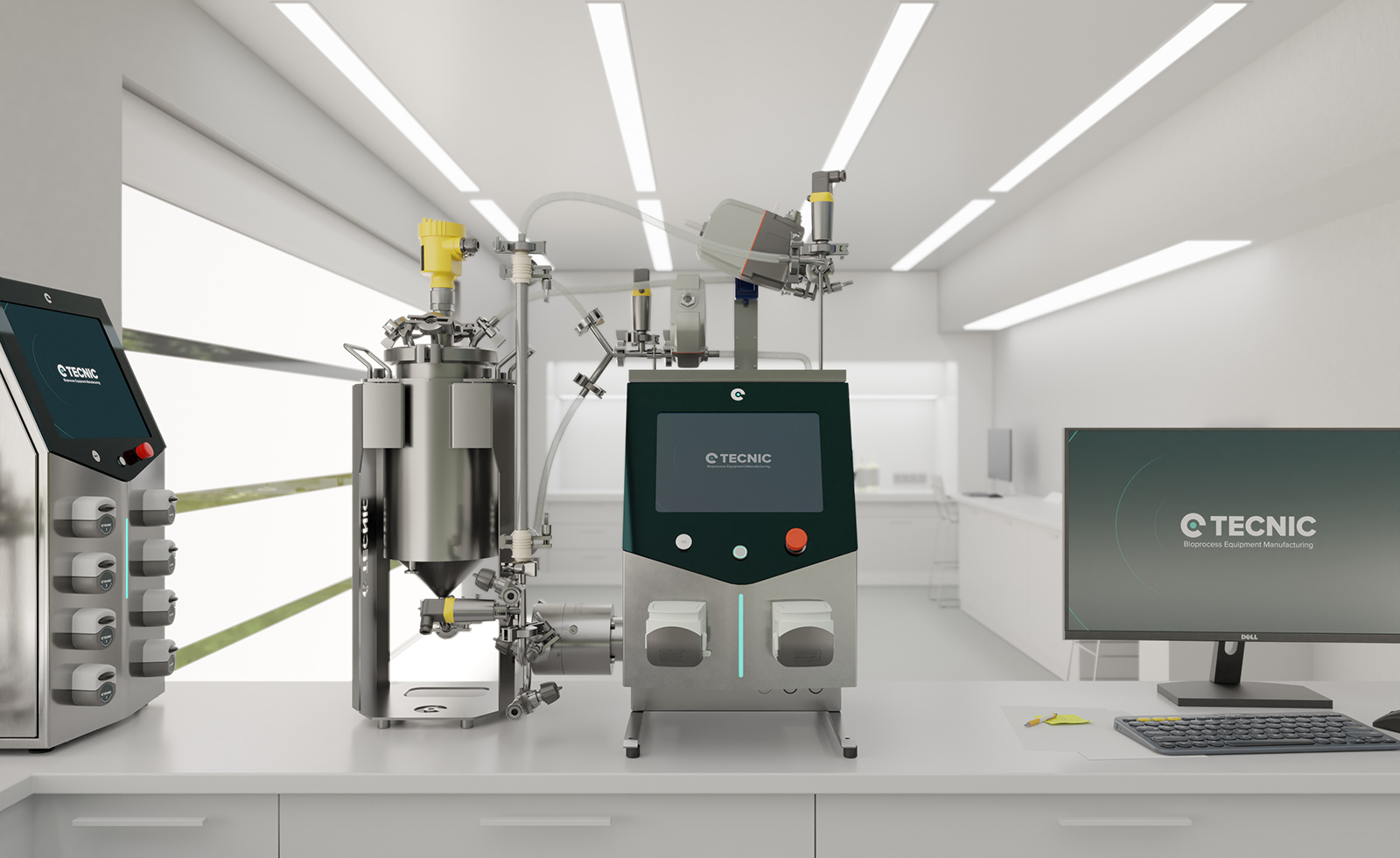
At TECNIC, we integrate the DTS heat exchanger as part of our solutions for GMP environments. Its implementation responds not only to regulatory requirements but also to our commitment to process quality and final product safety. Thanks to this type of technology, our solutions ensure not only high thermal performance but also maximum confidence in the critical operations of our clients.

Double Tube Sheet Heat Exchangers FAQ

Frequently Asked Questions (FAQ)

1. What is a double tube sheet heat exchanger?

It’s a shell-and-tube heat exchanger with two separate tube sheets that prevent cross-contamination between fluids.

2. Why are double tube sheet exchangers used in biopharma?

To ensure sterile fluid separation and early leak detection in critical applications like WFI, pure steam, and vaccine production.

3. How does a double tube sheet exchanger detect leaks?

Leaks are diverted to a vented chamber between tube sheets, allowing visual or sensor-based detection before contamination occurs.

4. Are double tube sheet exchangers GMP compliant?

Yes, Double Tube Sheet designs are recognized by FDA and other regulatory bodies as best practice for avoiding contamination in pharmaceutical systems.

5. What fluids are typically involved?

High-purity water, clean steam, product solutions, and utility fluids like industrial steam or glycol.

6. Is maintenance more complex than in standard exchangers?

No. Double Tube Sheet exchangers offer easier inspection and fewer gaskets, often simplifying maintenance tasks.

7. Does the double tube sheet design affect thermal efficiency?

No. These exchangers maintain excellent thermal performance while enhancing safety and reliability.

Subscribe to our newsletter

Newsletter Form

Contact form

Your opinion is very important to us, and we encourage you to contact our sales team to discuss the purchase of our bioprocess equipment. We are here to answer your questions and help you find the best solution for your needs.

Quote
Related Content

Quote

Quote
Image to access to all TECNIC's features, you can see a person working with the ePilot Bioreactor.

Coming soon 

We are finalizing the details of our new equipment. Soon, we will announce all the updates. If you want to receive all the latest news about our products, subscribe to our newsletter or follow our social media channels. 

Newsletter Form

Sign Up

Stay informed about our product innovations, best practices, exciting events and much more! After signing up for our newsletter, you can unsubscribe at any time.

Newsletter Form

Cassette

We understand the importance of flexibility and efficiency in laboratory processes. That's why our equipment is designed to be compatible with Cassette filters, an advanced solution for a variety of filtration applications. Although we do not manufacture the filters directly, our systems are optimized to take full advantage of the benefits that Cassette filters offer.

Cassette filters are known for their high filtration capacity and efficiency in separation, making them ideal for ultrafiltration, microfiltration, and nanofiltration applications. By integrating these filters into our equipment, we facilitate faster and more effective processes, ensuring high-quality results.

Our equipment, being compatible with Cassette filters, offers greater versatility and adaptability. This means you can choose the filter that best suits your specific needs, ensuring that each experiment or production process is carried out with maximum efficiency and precision.

Moreover, our equipment stands out for its 100% automation capabilities. Utilizing advanced proportional valves, we ensure precise control over differential pressure, transmembrane pressure, and flow rate. This automation not only enhances the efficiency and accuracy of the filtration process but also significantly reduces manual intervention, making our systems highly reliable and user-friendly.

Hollow Fiber

We recognize the crucial role of flexibility and efficiency in laboratory processes. That's why our equipment is meticulously designed to be compatible with Hollow Fiber filters, providing an advanced solution for a broad spectrum of filtration applications. While we don't directly manufacture these filters, our systems are finely tuned to harness the full potential of Hollow Fiber filters.

Hollow Fiber filters are renowned for their exceptional performance in terms of filtration efficiency and capacity. They are particularly effective for applications requiring gentle handling of samples, such as in cell culture and sensitive biomolecular processes. By integrating these filters with our equipment, we enable more efficient, faster, and higher-quality filtration processes.

What sets our equipment apart is its 100% automation capability. Through the use of sophisticated proportional valves, our systems achieve meticulous control over differential pressure, transmembrane pressure, and flow rate. This level of automation not only boosts the efficiency and precision of the filtration process but also significantly diminishes the need for manual oversight, rendering our systems exceptionally reliable and user-friendly.

Contact General

Cellular configuration

The cellular configuration of the eLab Advanced is equipped with a pitched-blade impeller designed to support efficient mixing for cell culture processes in both laboratory development and early scale-up. The blade geometry promotes mainly axial flow, helping to distribute gases, nutrients and pH control agents uniformly throughout the vessel while keeping shear stress at a moderate level. This makes it suitable for mammalian, insect and other shear-sensitive cell lines when operated with appropriate agitation and aeration settings. In combination with the vessel aspect ratio and baffle design, the pitched blade supports stable foaming behavior and reproducible oxygen transfer, which is essential when comparing batches or transferring processes between working volumes.

Operators can fine-tune agitation speed to balance oxygen demand and mixing time without excessively increasing mechanical stress on the culture. 

Microbial configuration

The microbial configuration of the eLab Advanced is equipped with a Rushton turbine specifically designed for high-oxygen-demand processes such as bacterial and yeast fermentations. The radial-flow impeller generates strong mixing and intense gas dispersion, promoting high oxygen transfer rates and fast homogenization of nutrients, antifoam and pH control agents throughout the vessel. This makes it particularly suitable for robust microbial strains operating at elevated agitation speeds and aeration rates.

Operators can adjust agitation and gas flow to reach the required kLa while maintaining consistent mixing times, even at high cell densities. This configuration is an excellent option for users who need a powerful, reliable platform to develop and optimize microbial processes before transferring them to pilot or production scales.

Cellular configuration

The cellular configuration of the eLab Advanced is equipped with a pitched-blade impeller designed to support efficient mixing for cell culture processes in both laboratory development and early scale-up. The blade geometry promotes mainly axial flow, helping to distribute gases, nutrients and pH control agents uniformly throughout the vessel while keeping shear stress at a moderate level. This makes it suitable for mammalian, insect and other shear-sensitive cell lines when operated with appropriate agitation and aeration settings. In combination with the vessel aspect ratio and baffle design, the pitched blade supports stable foaming behavior and reproducible oxygen transfer, which is essential when comparing batches or transferring processes between working volumes.

Operators can fine-tune agitation speed to balance oxygen demand and mixing time without excessively increasing mechanical stress on the culture. 

Technical specifications

Materials and finishes

Typical
  • Product-contact parts: AISI 316L (1.4404), typical Ra < 0.4 µm (16 µin)
  • Non-contact parts/skid: AISI 304/304L
  • Seals/elastomers: platinum-cured silicone, EPDM and/or PTFE (material set depends on selection)
  • Elastomers compliance (depending on selected materials): FDA 21 CFR 177.2600 and USP Class VI
  • Surface treatments: degreasing, pickling and passivation (ASTM A380 and ASTM A968)
  • Roughness control on product-contact surfaces

Design conditions

Pressure & temperature

Defined considering non-hazardous process fluids (PED group 2) and jacket steam/superheated water (PED group 5), depending on configuration and project scope.

Reference design envelope
ModeElementWorking pressure (bar[g])Working pressure (psi[g])T max (°C / °F)
ProcessVessel0 / +2.50 / +36.3+90 / 194
ProcessJacket0 / +3.80 / +55.1+90 / 194
SterilisationVessel0 / +2.50 / +36.3+130 / 266
SterilisationJacket0 / +3.80 / +55.1+150 / 302
Jacket working pressure may also be specified as 0 / +4 bar(g) (0 / +58.0 psi[g]) depending on design selection; final values are confirmed per project.

Pressure control and safeguards

Typical
  • Designed to maintain a vessel pressure set-point typically in the range 0 to 2.5 bar(g)
  • Aseptic operation commonly around 0.2 to 0.5 bar(g) to keep the vessel slightly pressurised
  • Overpressure/underpressure safeguards included per configuration and regulations
  • Pressure safety device (e.g., rupture disc and/or safety valve) included according to configuration

Agitation

Reference ranges
Working volumeMU (Cell culture), referenceMB (Microbial), reference
10 L0 to 300 rpm0 to 1000 rpm
20 L0 to 250 rpm0 to 1000 rpm
30 L0 to 200 rpm0 to 1000 rpm
50 L0 to 180 rpm0 to 1000 rpm

Integrated peristaltic pumps (additions)

Typical

The equipment typically includes 4 integrated variable-speed peristaltic pumps for sterile additions (acid/base/antifoam/feeds). Actual flow depends on selected tubing and calibration.

ParameterTypical valueNotes
Quantity4 units (integrated)In control tower; assignment defined by configuration
Speed0-300 rpmVariable control from eSCADA
Minimum flow0-10 mL/minExample with 0.8 mm ID tubing; depends on tubing and calibration
Maximum flowUp to ~366 mL/minExample with 4.8 mm ID tubing; actual flow depends on calibration
Operating modesOFF / AUTO / MANUAL / PROFILEAUTO typically associated to pH/DO/foam loops or recipe
FunctionsPURGE, calibration, totaliser, PWMPWM available for low flow setpoints below minimum operating level

Gas flow control (microbial reference capacity)

Reference

For microbial culture (MB), gas flow controllers (MFC) are typically sized based on VVM targets. Typical reference VVM range: 0.5-1.5 (to be confirmed by process).

Working volume (L)VVM minVVM maxAir (L/min)O2 (10%) (L/min)CO2 (20%) (L/min)N2 (10%) (L/min)
100.51.55-150.5-1.51-30.5-1.5
200.51.510-301-32-61-3
300.51.515-451.5-4.53-91.5-4.5
500.51.525-752.5-7.55-152.5-7.5
O2/CO2/N2 values are shown as reference capacities for typical gas blending strategies (10% O2, 20% CO2, 10% N2). Final gas list and ranges depend on process and configuration.

Instrumentation and sensors

Typical

Instrumentation is configurable. The following list describes typical sensors integrated in standard configurations, plus common optional PAT sensors.

Variable / functionTypical technology / interfaceStatus (STD/OPT)
Temperature (process/jacket)Pt100 class A RTDSTD
Pressure (vessel/lines)Pressure transmitter (4-20 mA / digital)STD
Level (working volume)Adjustable probeSTD
pHDigital pH sensor (ARC or equivalent)STD
DO (pO2)Digital optical DO sensor (ARC or equivalent)STD
FoamConductive/capacitive foam sensorSTD
Weight / mass balanceLoad cell (integrated in skid)STD
pCO2Digital pCO2 sensor (ARC or equivalent)OPT
Biomass (permittivity)In-line or in-vessel sensorOPT
VCD / TCDIn-situ cell density sensorsOPT (MU)
Off-gas (O2/CO2)Gas analyser for OUR/CEROPT
ORP / RedoxDigital ORPOPT
Glucose / LactatePAT sensorOPT

Automation, software and connectivity

Typical

The platform incorporates TECNIC eSCADA (typically eSCADA Advanced for ePILOT) to operate actuators and control loops, execute recipes and manage process data.

Main software functions
  • Main overview screen with process parameters and trends
  • Alarm management (real-time alarms and historical log) with acknowledgement and comment option
  • Manual/automatic modes for actuators and control loops
  • Recipe management with phases and transitions; parameter profiles (multi-step) for pumps and setpoints
  • Data logging with configurable period and export to CSV; PDF report generation
Common control loops
  • Temperature control (jacket heating/cooling)
  • Pressure control (headspace) with associated valve management
  • pH control via acid/base addition pumps and optional CO2 strategy
  • DO control with cascade strategies (agitation, air, O2, N2) depending on package and configuration
  • Foam control (foam sensor and automatic antifoam addition)
Data integrity and 21 CFR Part 11

Support for 21 CFR Part 11 / EU GMP Annex 11 is configuration- and project-dependent and requires customer procedures and validation (CSV).

Utilities

Reference

Utilities depend on final configuration (e.g., AutoSIP vs External SIP) and destination market (EU vs North America). The following values are typical reference points.

UtilityTypical service / configurationPressureFlow / powerNotes
ElectricalEU base: 400 VAC / 50 Hz (3~)N/AAutoSIP: 12 kW; External SIP: 5 kWNA option: 480 VAC / 60 Hz; cabinet/wiring per NEC/NFPA 70; UL/CSA as required
Process gasesAir / O2 / CO2 / N2Up to 2.5 bar(g) (36.3 psi)According to setpointTypical OD10 pneumatic connections; final list depends on package
Instrument airPneumatic valvesUp to 6 bar(g) (87.0 psi)N/ADry/filtered air recommended
Cooling waterJacket cooling water2 bar(g) (29.0 psi)25 L/min (6.6 gpm)6-10 °C (43-50 °F) typical
Cooling waterCondenser cooling water2 bar(g) (29.0 psi)1 L/min (0.26 gpm)6-10 °C (43-50 °F) typical
Steam (External SIP)Industrial steam2-3 bar(g) (29.0-43.5 psi)30 kg/h (66 lb/h)For SIP sequences
Steam (External SIP)Clean steam1.5 bar(g) (21.8 psi)8 kg/h (18 lb/h)Depending on plant strategy

Compliance and deliverables

Typical

Depending on destination and project scope, the regulatory basis may include European Directives (CE) and/or North American codes. The exact list is confirmed per project and stated in the Declaration(s) of Conformity when applicable.

ScopeEU (typical references)North America (typical references)
Pressure equipmentPED 2014/68/EUASME BPVC Section VIII (where applicable)
Hygienic designHygienic design good practicesASME BPE (reference for bioprocessing)
Machine safetyMachinery: 2006/42/EC (until 13/01/2027) / (EU) 2023/1230OSHA expectations; NFPA 79 (industrial machinery) - project dependent
Electrical / EMCLVD 2014/35/EU; EMC 2014/30/EUNEC/NFPA 70; UL/CSA components and marking as required
Materials contactEC 1935/2004 + EC 2023/2006 (GMP for materials) where applicableFDA 21 CFR (e.g., 177.2600 for elastomers) - materials compliance
Software / CSVEU GMP Annex 11 (if applicable)21 CFR Part 11 (if applicable)
Standard documentation package
  • User manual and basic operating instructions
  • P&ID / layout drawings as per project scope
  • Material certificates and finish/treatment certificates (scope dependent)
  • FAT report (if included in contract)
Optional qualification and commissioning services
  • SAT (Site Acceptance Test)
  • IQ / OQ documentation and/or execution (scope agreed with customer)
  • CSV support package for regulated environments (ALCOA+ considerations, backups, time synchronisation, etc.)

Ordering and configuration

Project-based

ePILOT BR is configured per project. To define the right MU/MB package, volumes and options (utilities, sensors, software and compliance), please contact TECNIC with your URS or request the configuration questionnaire.

The information provided above is for general reference only and may be modified, updated or discontinued at any time without prior notice. Values and specifications are indicative and may vary depending on project scope, configuration and applicable requirements. This content does not constitute a binding offer, warranty, or contractual commitment. Any final specifications, deliverables and acceptance criteria will be confirmed in the corresponding quotation, technical documentation and/or contract documents.

Cellular configuration

The cellular configuration of the eLab Advanced is equipped with a pitched-blade impeller designed to support efficient mixing for cell culture processes in both laboratory development and early scale-up. The blade geometry promotes mainly axial flow, helping to distribute gases, nutrients and pH control agents uniformly throughout the vessel while keeping shear stress at a moderate level. This makes it suitable for mammalian, insect and other shear-sensitive cell lines when operated with appropriate agitation and aeration settings. In combination with the vessel aspect ratio and baffle design, the pitched blade supports stable foaming behavior and reproducible oxygen transfer, which is essential when comparing batches or transferring processes between working volumes.

Operators can fine-tune agitation speed to balance oxygen demand and mixing time without excessively increasing mechanical stress on the culture. 

Technical specifications

    ePILOT BR configuration questionnaire


    Project details


    FAT:

    Shipment:

    Installation:

    SAT:

    IQ/OQ:


    Process and automation requirements


    MU only (cell culture)


    MB only (microbial)


    Utilities and infrastructure


    North America specific


    Connections, consumables and compliance


    EU specific


    North America specific


    Software / CSV (GMP)


    Validation, testing and documentation


    GMP / CSV


    Logistics and installation


    Additional comments