What is tangential flow filtration?
Tangential flow filtration (TFF), also known as cross-flow filtration, is a filtration method where the feed liquid flows parallel (tangential) to the membrane surface rather than directly through it.
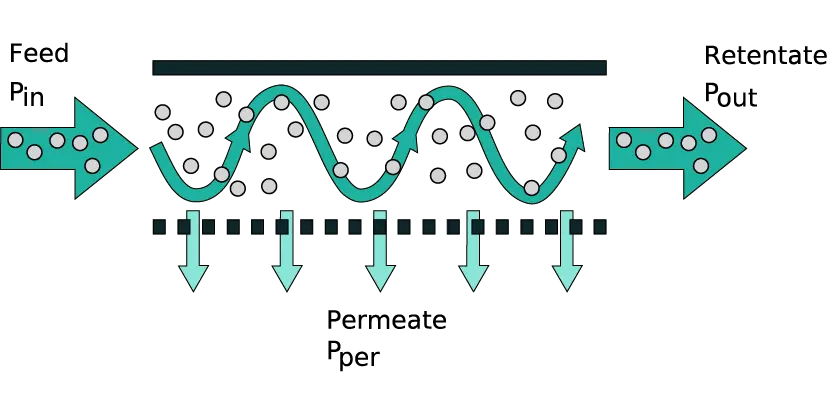
In a TFF system, a pump continuously recirculates the feed solution across the membrane. A portion of the fluid (containing smaller molecules and solvent) passes through the membrane as permeate, while larger molecules are retained and returned as retentate. The tangential (sideways) movement of the fluid creates a sweeping effect that helps prevent particles from building up on the membrane surface. This is in contrast to normal “dead-end” filtration, where flow is perpendicular and solids rapidly accumulate as a filter cake.
How does a TFF system work?
A pressure difference across the membrane (known as the transmembrane pressure, TMP) drives solvent and small solutes through the membrane pores. Meanwhile, the tangential flow of the feed continuously washes the membrane, minimizing fouling.
The retained molecules remain in the flowing stream and can be recirculated for further filtration. This design keeps the filtration performance more consistent over time and allows processing to continue until the desired concentration or separation is achieved. In practical terms, TFF can handle larger volumes or higher concentrations than a comparable normal flow filter because the tangential motion mitigates clogging and maintains flux (flow rate through the membrane) for longer.
What is the difference between tangential flow filtration and normal flow filtration?
Normal flow filtration (NFF), also called direct flow or dead-end filtration, is the traditional method where the fluid is pushed directly through a filter membrane (perpendicular to it). All fluid flow is into the membrane, so anything larger than the pore size accumulates on the filter surface, forming a residue layer (filter cake). Over time this cake clogs the filter, reducing flow and efficiency. In other words, normal flow filtration is like pouring liquid straight through a sieve: the sieve catches debris, which can quickly block further flow.
Tangential flow filtration (TFF), by contrast, sends the fluid across the membrane surface (parallel to it) rather than straight through. Only a portion of the fluid passes through at any moment; the rest sweeps along the membrane, carrying away retained particles. This cross-flow action prevents the buildup of a thick cake layer and significantly slows down fouling. As a result, TFF can maintain a more stable filtration rate and extend the membrane’s usable life. Additionally, TFF allows continuous processing, you can recirculate retentate and even perform concentration and diafiltration in the same run (more on diafiltration below). Normal flow filters, on the other hand, often need to be replaced or cleaned once they clog.
In summary, the key difference is how the fluid is oriented relative to the membrane: NFF (dead-end) pushes fluid directly through, which is simple but prone to clogging, whereas TFF (cross-flow) runs fluid across the membrane, reducing clogging and enabling high-efficiency filtration of biomolecules. TFF generally requires more complex equipment (pump, recirculation loop) than a single-use normal filter, but it offers better performance for many bioprocess applications
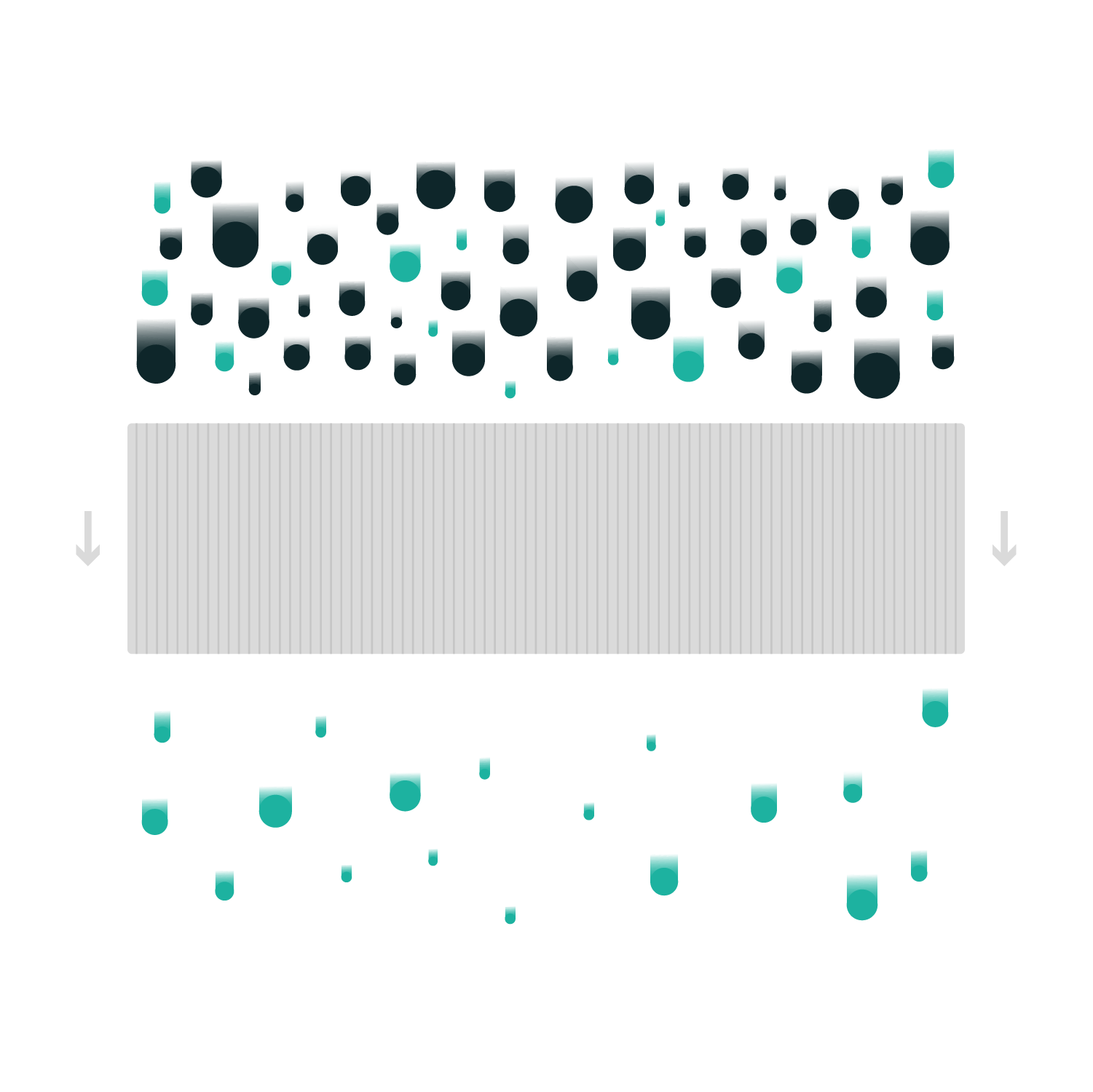
Normal flow filtration
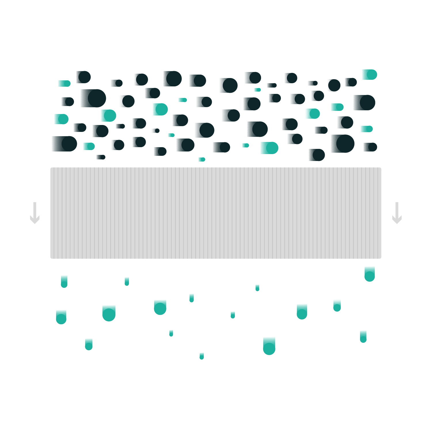
Tangential flow filtration
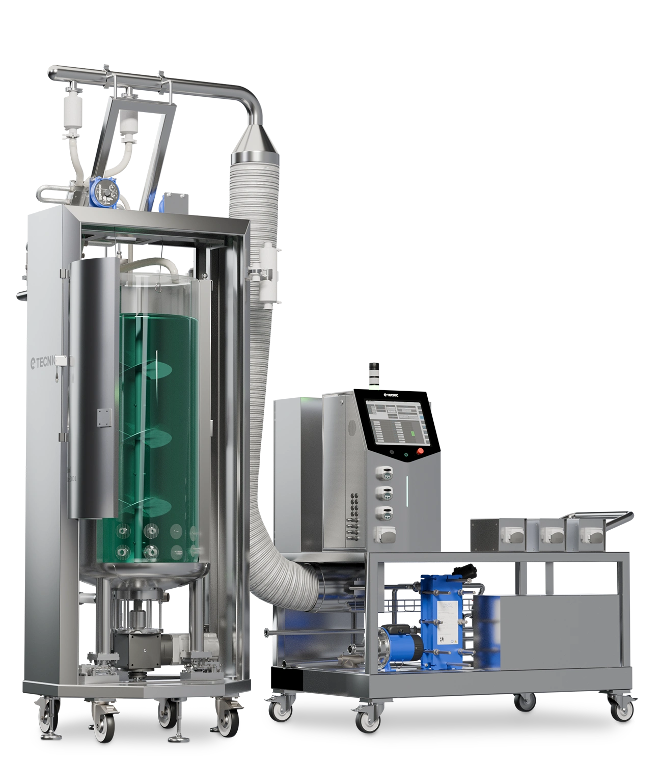
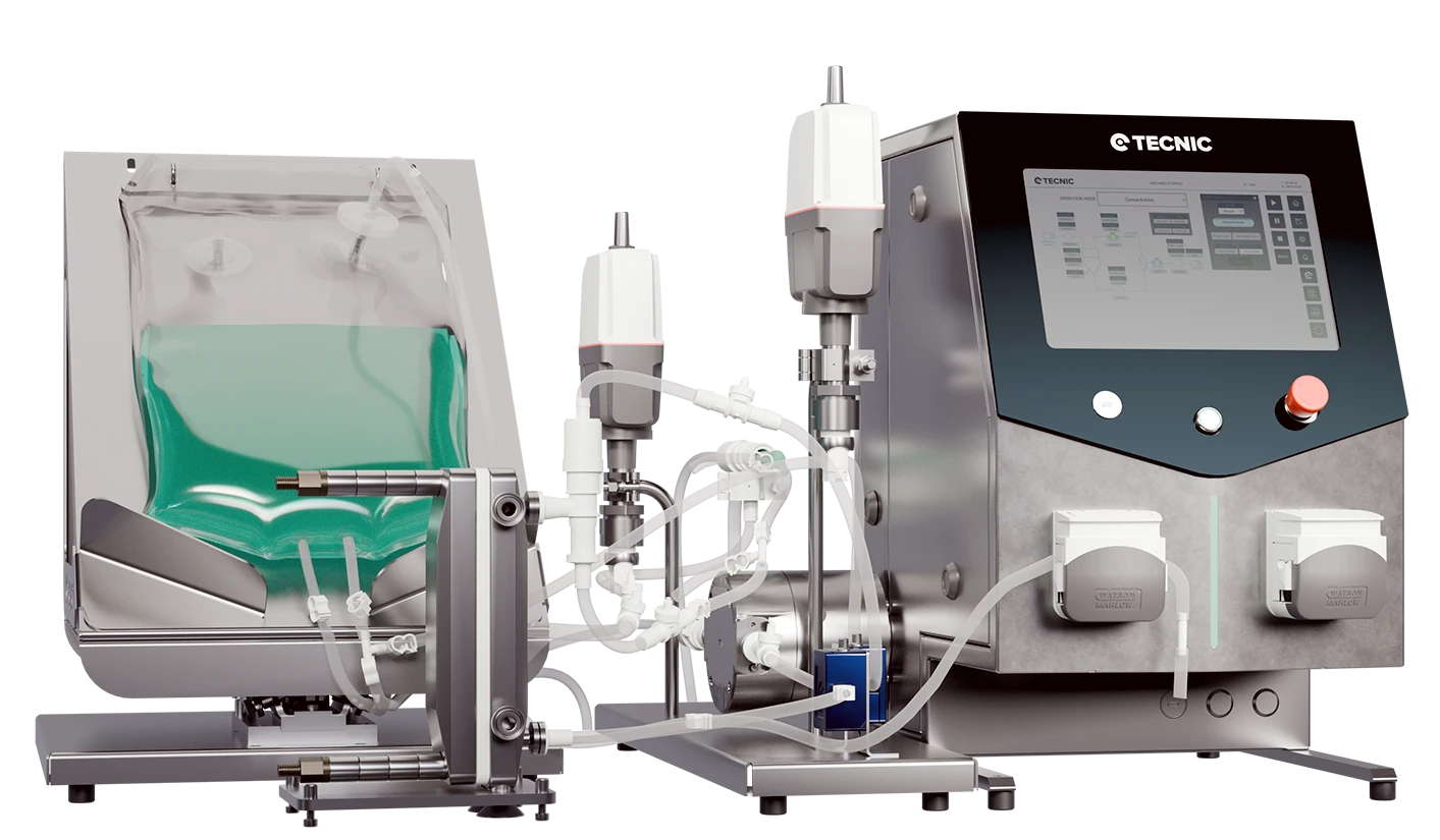
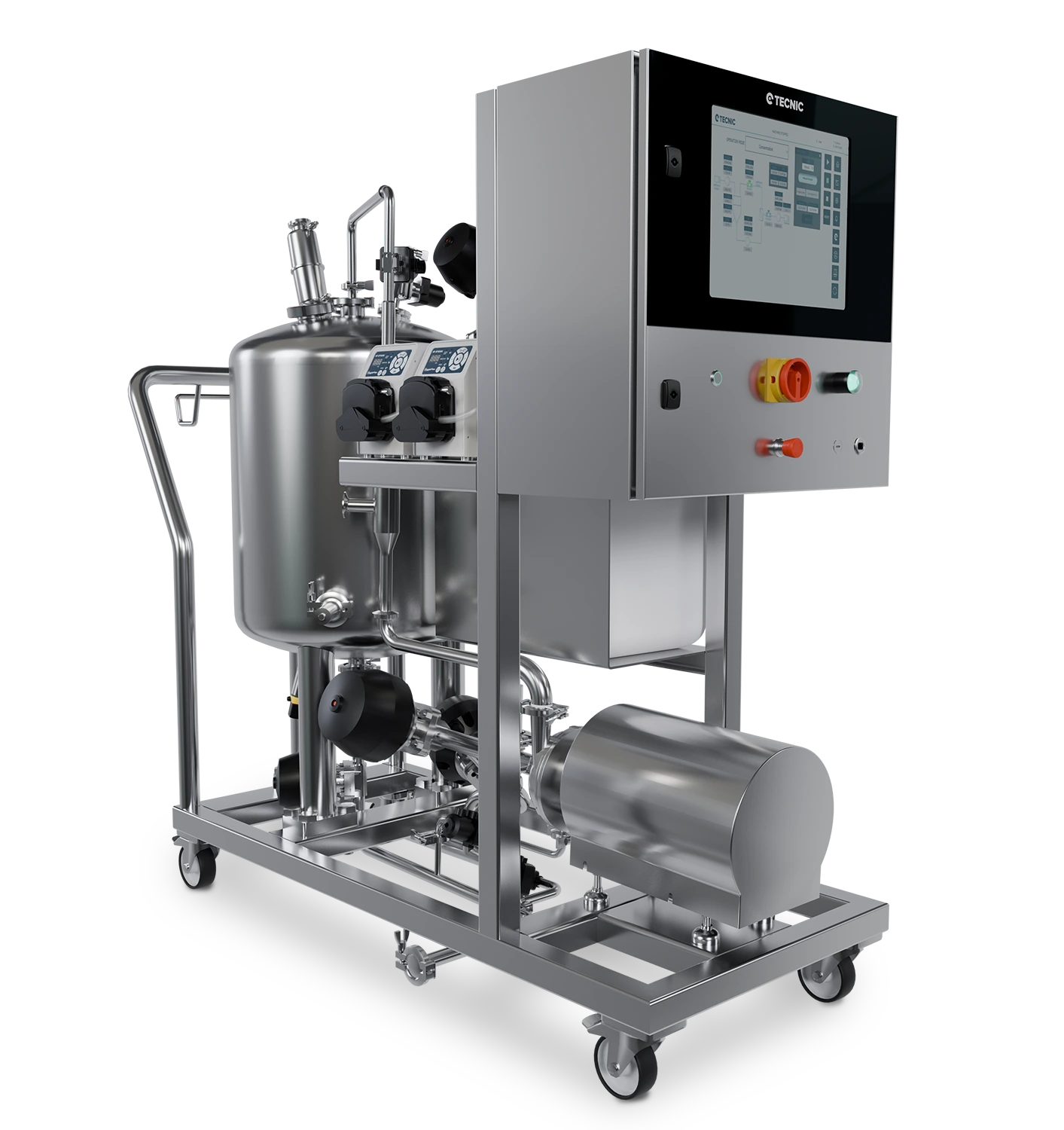
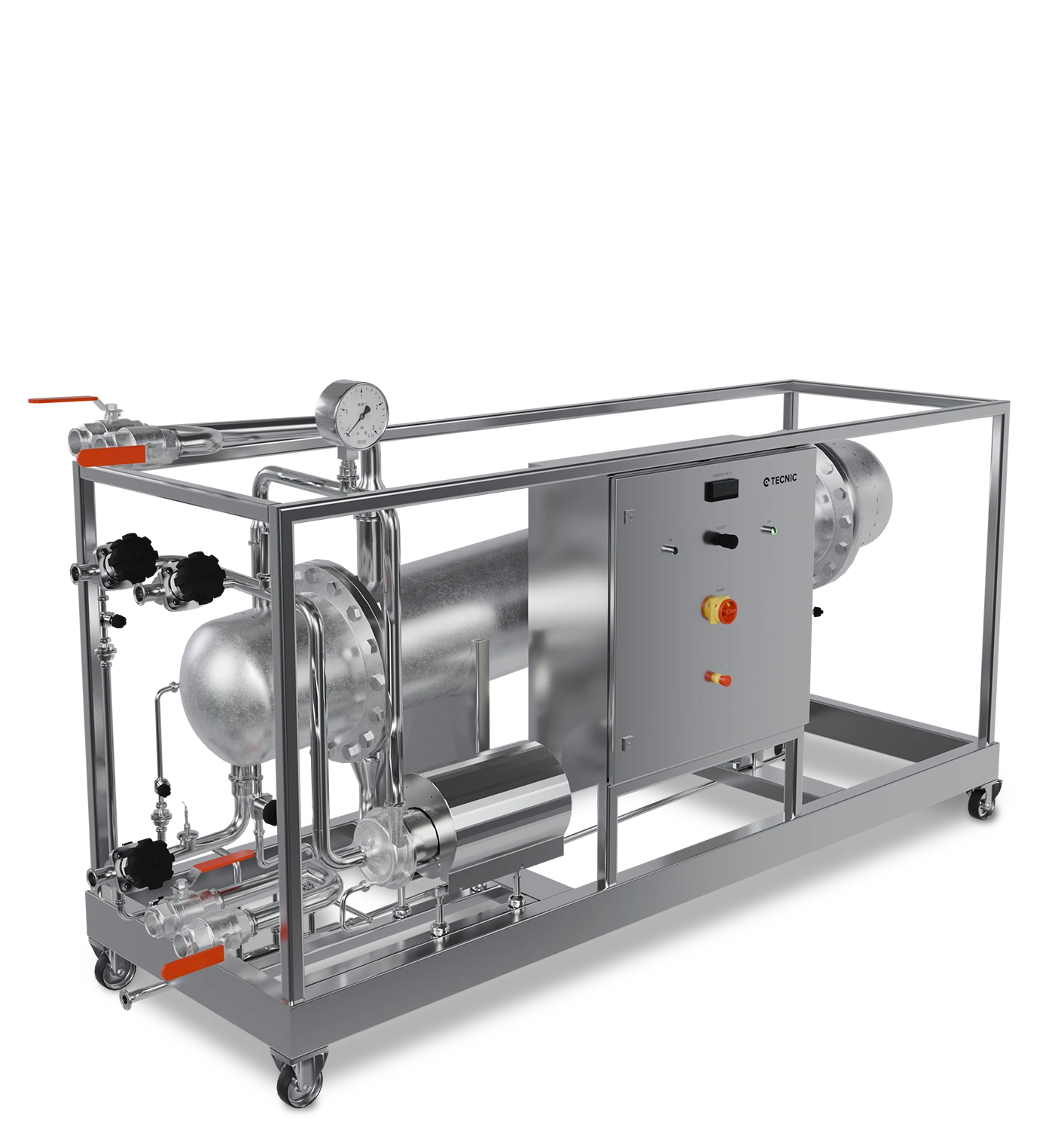
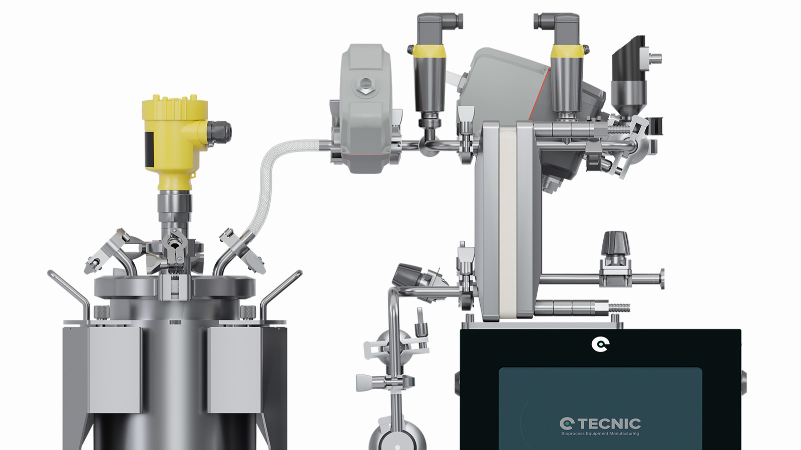
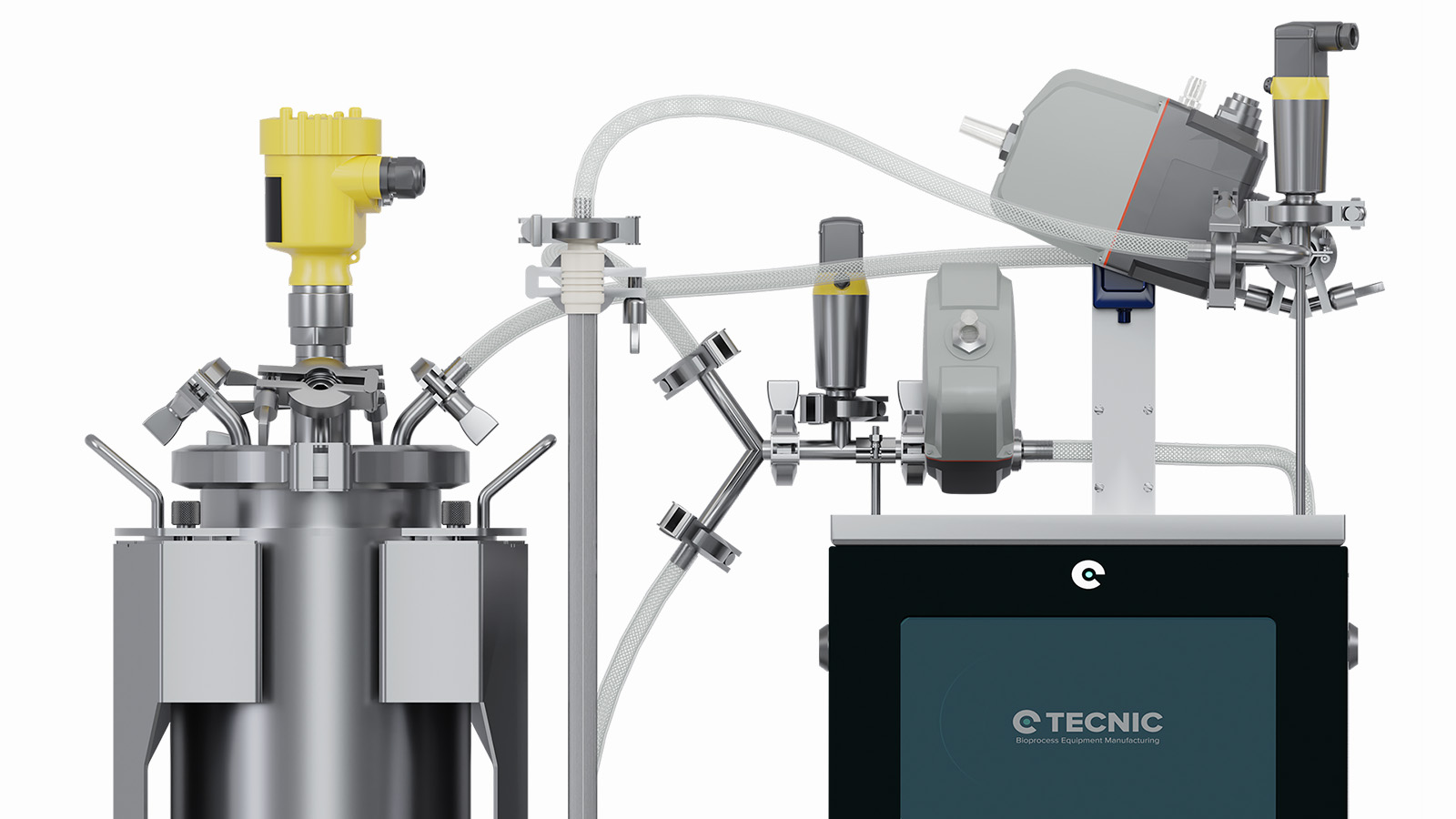
What are the main components of a TFF system?
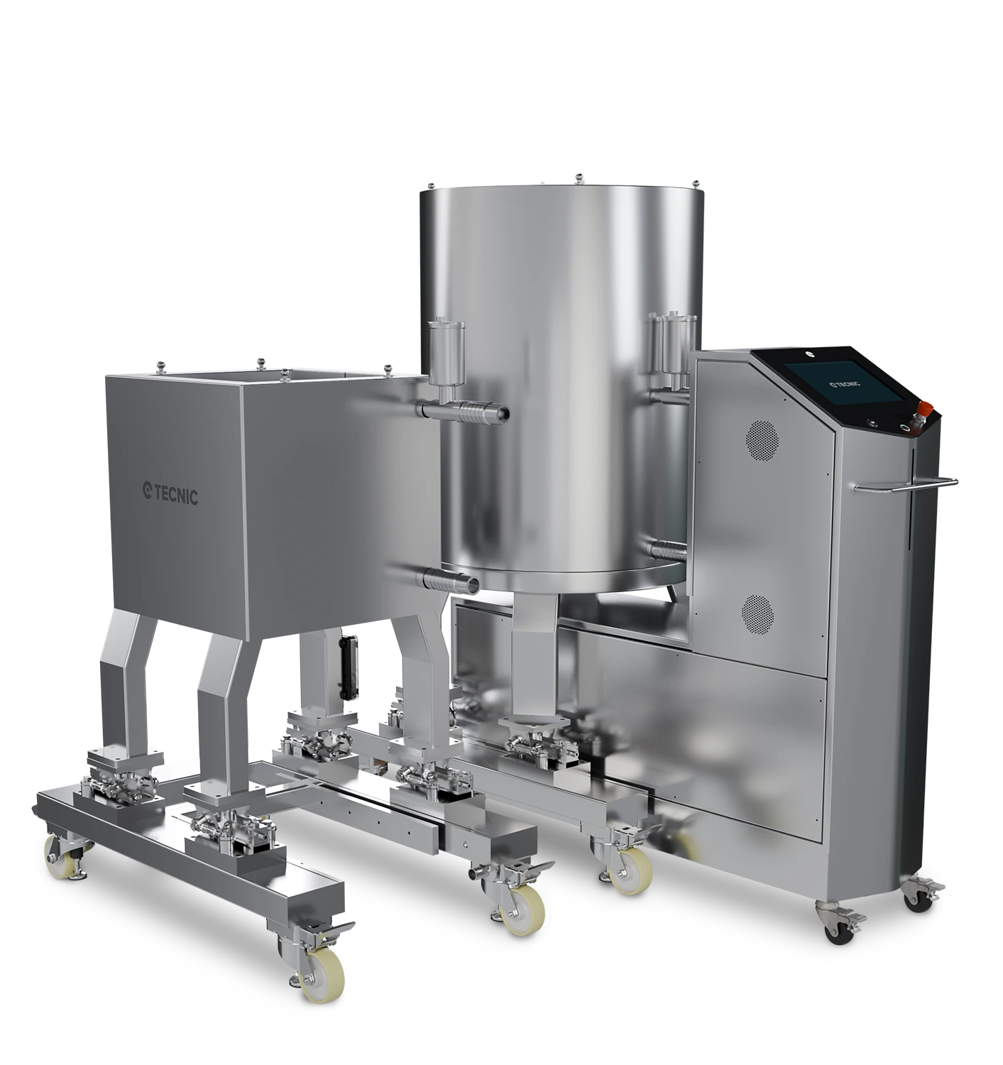
A tangential flow filtration system is typically set up in a circulating loop configuration. Key components of a TFF system include:
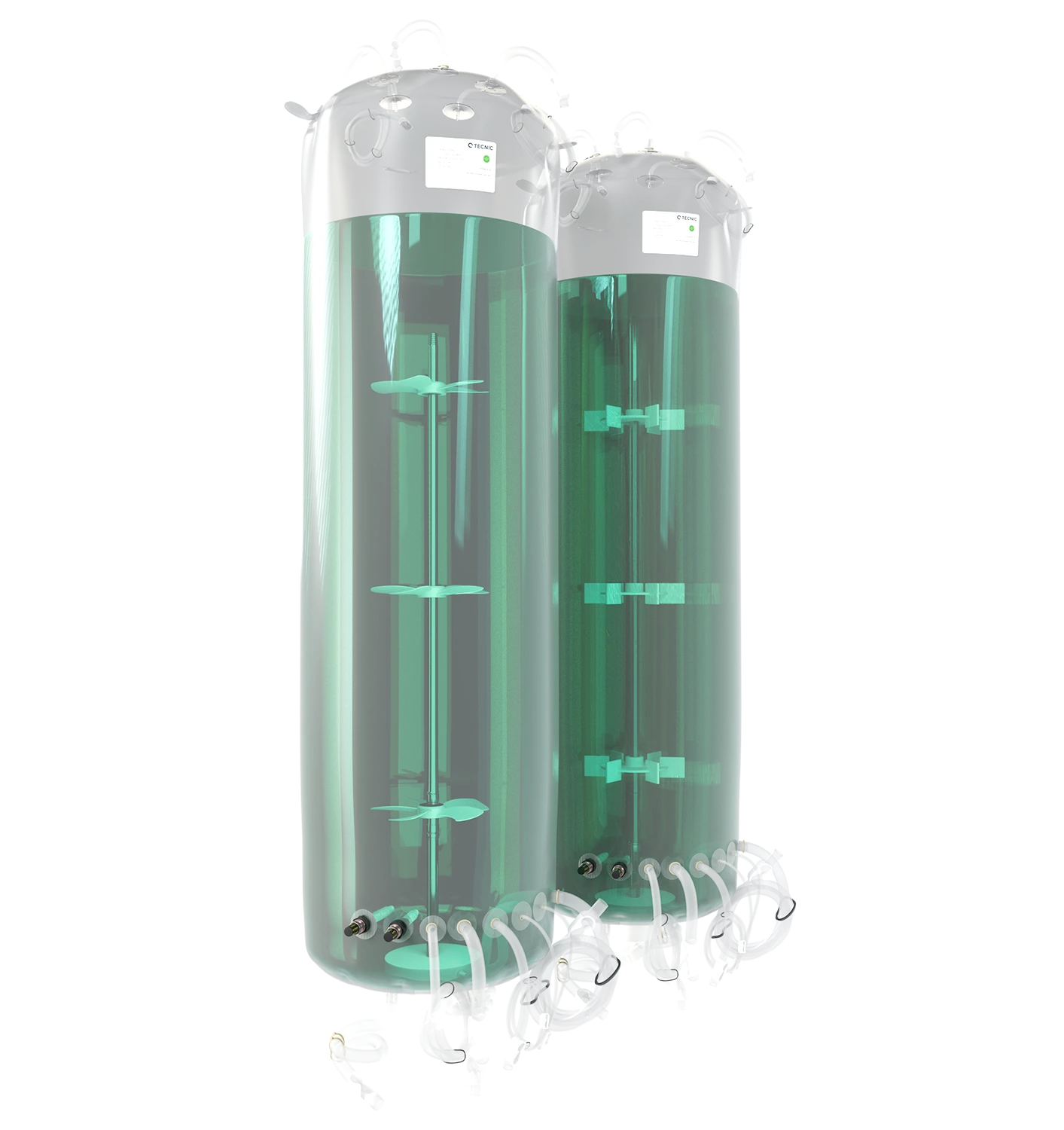
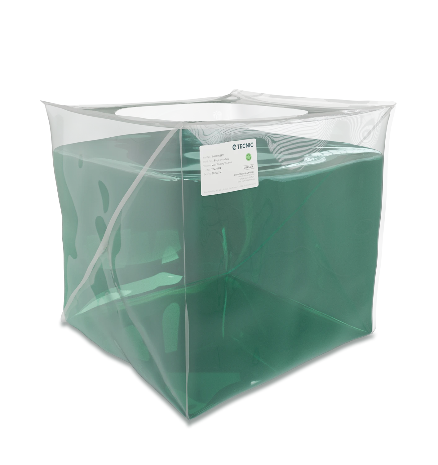
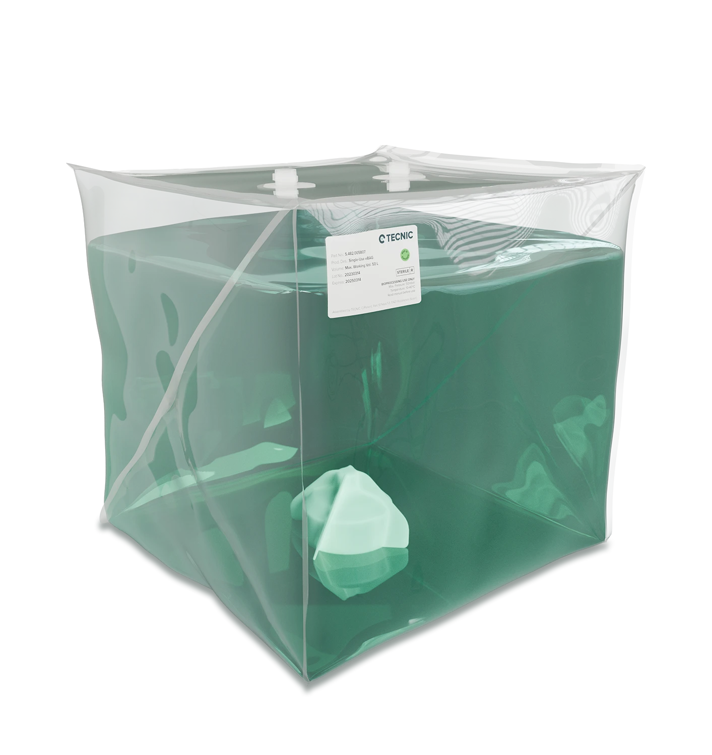
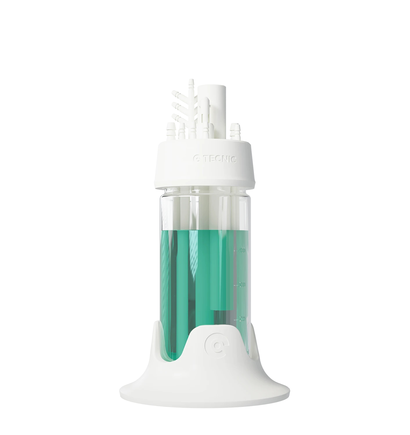
Feed Reservoir: Holds the solution to be filtered (e.g. a cell culture harvest or protein solution). In small lab setups, this might be a beaker or bag; in larger systems, a feed tank.
Pump: Drives the circulation of the feed through the system. Commonly a peristaltic pump or diaphragm pump is used to push the feed liquid at a controlled flow rate along the membrane module.
TFF Membrane Module: The filter unit where separation occurs. It can be a cassette (flat sheet membranes in a holder) or a hollow fiber cartridge (bundle of tiny tubular membranes), which we discuss in detail below. The module has an inlet for feed, an outlet for retentate (the portion that did not pass through the membrane), and a permeate outlet (for the filtered fluid that passes through the membrane).
Pressure Control & Monitors: Pressure gauges or sensors are placed at the inlet and outlet of the membrane module to monitor the pressure drop and transmembrane pressure (TMP). A valve on the retentate line is often used to control back-pressure, which in turn controls the TMP. Maintaining the correct pressure is critical, too low and filtration is slow; too high and the membrane or product could be damaged.
Retentate Loop: The retentate (concentrated fluid that exits the membrane module without passing through) is either circulated back to the feed reservoir for continued filtration or sent to waste if the process is continuous. In a closed-loop batch TFF process, the retentate continuously returns to the feed tank, gradually increasing in concentration with each pass.
Permeate Collection: The permeate (filtered liquid that has passed through the membrane) is collected in a separate container. This fraction contains the small molecules or solvents that passed through. In many cases, the permeate is waste (e.g. water, salts removed during concentration), but in some applications the permeate is the product (for example, if filtering out cells to collect a virus or protein that is small enough to pass through).
Flow path: The pump draws feed from the reservoir and propels it into the TFF membrane module. Inside the module, the feed flows along the membrane surface. Because of the pressure, some portion of the liquid filters through the membrane as permeate. The rest (retentate) carries the retained larger components forward and out of the module. The retentate then either recirculates back to the reservoir for another pass or exits if you’re running in a continuous mode. By adjusting the flow rate and retentate back-pressure, operators control the filtration rate and the degree of concentration. The process continues until the desired volume is filtered or the target concentration is reached. Throughout, the cross-flow minimizes membrane fouling by continuously rinsing the surface.
What are the main types of TFF equipment?
TFF systems come in a few different hardware configurations, primarily distinguished by the type of membrane module used. The two most common TFF module formats are flat-sheet cassettes and hollow fiber modules. Each type has its own design and is suited to different needs.
What is a TFF cassette filter?
A TFF cassette (also called a flat sheet cassette) is a module that contains flat membrane sheets stacked together in a holder (frame). Each sheet is separated by shallow spacer screens that create parallel flow channels. When assembled, the cassette has an inlet and outlet for the feed/retentate flow across the membrane surface, and ports for permeate collection. The design forces the feed to flow through the narrow screen channels, creating turbulent flow across the membrane. This turbulence improves mixing at the surface and helps prevent polarization or fouling of the membrane.
TFF cassettes typically offer high filtration flux (flow per area) and can accommodate large membrane surface areas by stacking multiple sheets. They are often used in processes that demand high throughput. However, flat cassette systems may subject the fluid to higher shear forces (due to turbulence and pumping) compared to some other formats. They work well for robust proteins or virus particles that can handle shear, for example, non-enveloped viruses like adeno-associated virus (AAV) benefit from the high flux of flat-sheet cassettes and are not particularly sensitive to shear. Cassette modules generally require a housing (holder) that clamps the cassette in place and provides seals for the flow paths, which adds to the equipment setup.
What is a hollow fiber TFF filter?
hollow fiber module contains dozens or hundreds of tiny hollow fiber capillaries (think of them as very thin straws) bundled together. The interior of each fiber is a tubular membrane. The feed is pumped through the inside of these fibers (the lumen). The membrane walls allow permeate to pass through to the outside of the fibers, while retentate continues down the lumen and exits at the fiber ends. Hollow fiber TFF modules provide a self-contained cartridge format, they often look like cylindrical cartridges with ports for feed/retentate and permeate. The flow in hollow fibers tends to be more laminar (smooth) because the channels are narrow and there is no mesh spacer to induce turbulence. This means hollow fiber systems operate at lower shear stress, making them gentler on shear-sensitive products like fragile proteins, cells, or enveloped viruses (e.g. lentivirus).
Hollow fiber TFF modules usually have a high surface-area-to-volume ratio, meaning they can pack a lot of membrane area in a compact module. They are available in a range of sizes (from small lab-scale cartridges to large industrial modules) and do not require a separate holding cassette, you simply connect the cartridge. They can be easier to set up and replace. Another advantage is that many hollow fiber modules can be back-flushed or backwashed to help remove fouling; this is possible because the fibers are a self-supporting structure. On the downside, hollow fiber modules often have lower flow turbulence, which can lead to some concentration polarization (buildup of solutes at the membrane surface) if not managed, potentially reducing flux over time. They also might be less tolerant of very high feed pressures. But for applications requiring gentle handling (for example, processing shear-sensitive molecules or cells), hollow fiber TFF is ideal.
Both cassette and hollow fiber systems are widely used. In fact, flat-sheet cassettes and hollow fibers are the preferred TFF formats in most laboratory and production settings. Some niche applications (like certain large-scale water or plasma filtrations) use spiral-wound membranes or ceramic membranes, but those are less common in biopharma process TFF. For most users, the choice comes down to cassette vs. hollow fiber, which we will discuss how to choose in a later section.
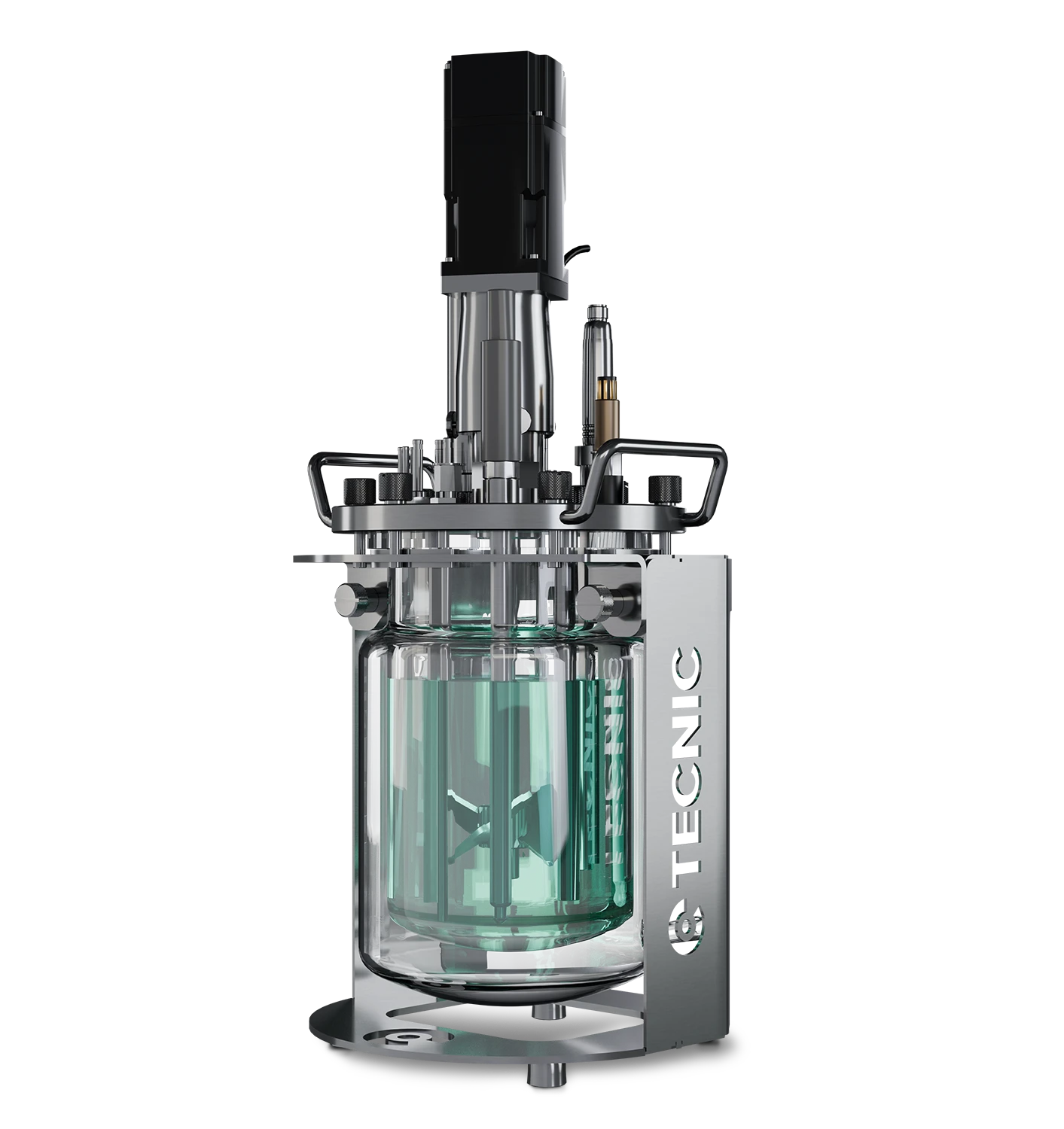
What is a TFF membrane and how does it function?
he TFF membrane is the heart of any tangential flow filtration system. It is a thin, semi-permeable barrier that allows certain molecules to pass through while blocking others based on size (and sometimes charge or other properties). In practice, TFF membranes are typically characterized by their pore size or molecular weight cutoff (MWCO), for example, a membrane might be rated 0.2 µm (micrometer) for microfiltration or 30 kDa (kilodalton) MWCO for ultrafiltration. This rating indicates what size of particles or molecules will be retained. Smaller molecules than the cutoff will pass through in the permeate, and larger molecules will be retained in the retentate.
In a TFF system, the membrane’s job is to perform the separation:
Microfiltration membranes (pore sizes ~0.1–0.45 µm) are used to separate cells or large debris from liquids (for example, harvesting cells or clarifying lysates). They let through fluids and very small particles but hold back whole cells, cell aggregates, and most bacteria.
Ultrafiltration membranes (MWCO in the 1–1000 kDa range, roughly corresponding to nanometer-scale pores) are used to separate or concentrate proteins, viruses, DNA, and other macromolecules. Ultrafiltration membranes are very useful for concentrating therapeutic proteins or viruses because they can retain those large biomolecules while water, salts, and smaller impurities pass through.
Nanofiltration membranes have an MWCO typically between 200 and 1000 Da, placing them between ultrafiltration and reverse osmosis in terms of selectivity. These membranes are used to remove small organic molecules, divalent salts, and residual solvents, while allowing most monovalent salts and water to pass. In biotech, nanofiltration is often used for buffer exchange, concentration of small peptides, or removal of endotoxins and antibiotics from process streams, where ultrafiltration may not offer enough selectivity.
Functionally, when the TFF system is running, the membrane allows the solvent (e.g. water) and any dissolved salts or small molecules to filter through to the permeate side. Meanwhile, the valuable product (like a protein or viral vector, if it’s larger than the membrane’s cutoff) is retained and continuously circulates on the feed/retentate side. Over time, the product becomes more concentrated in the retentate loop as permeate is removed. If the goal is purification, the membrane ensures that contaminants of a certain size are separated out.
Membranes are made from various materials such as polyethersulfone (PES), regenerated cellulose, or PVDF, chosen for compatibility with the product and cleaning chemicals. They are usually housed in either the cassette or hollow fiber format described above. A well-chosen membrane will have high product yield (minimal sticking or undesired passage of the target through the membrane) and low fouling tendencies. The membrane’s integrity and pore size uniformity are critical, operators often do an integrity test to ensure there are no leaks before use.
To summarize, a TFF membrane functions as a selective sieve: it lets the solvent and smaller components pass while retaining larger biomolecules. By running the fluid tangentially and controlling pressure, TFF systems use these membranes to achieve efficient separation without clogging. Proper membrane selection (pore size and material) is crucial to the success of the filtration process.
| Membrane Type | Typical MWCO / Pore Size | Key Applications | Key Characteristics |
|---|---|---|---|
| Microfiltration | ~0.1–0.45 µm | Cell harvesting, lysate clarification, bacteria removal | Retains cells and large debris; allows fluids and small particles to pass |
| Ultrafiltration | 1–1000 kDa (nanometer-scale pores) | Protein concentration, virus purification, DNA separation | Retains large biomolecules (proteins, viruses); removes salts, water, and small solutes |
| Ultrafiltration | ~200–1000 Da | Buffer exchange, small peptide concentration, endotoxin or solvent removal | Removes small organics and divalent salts; allows water and monovalent salts to pass |
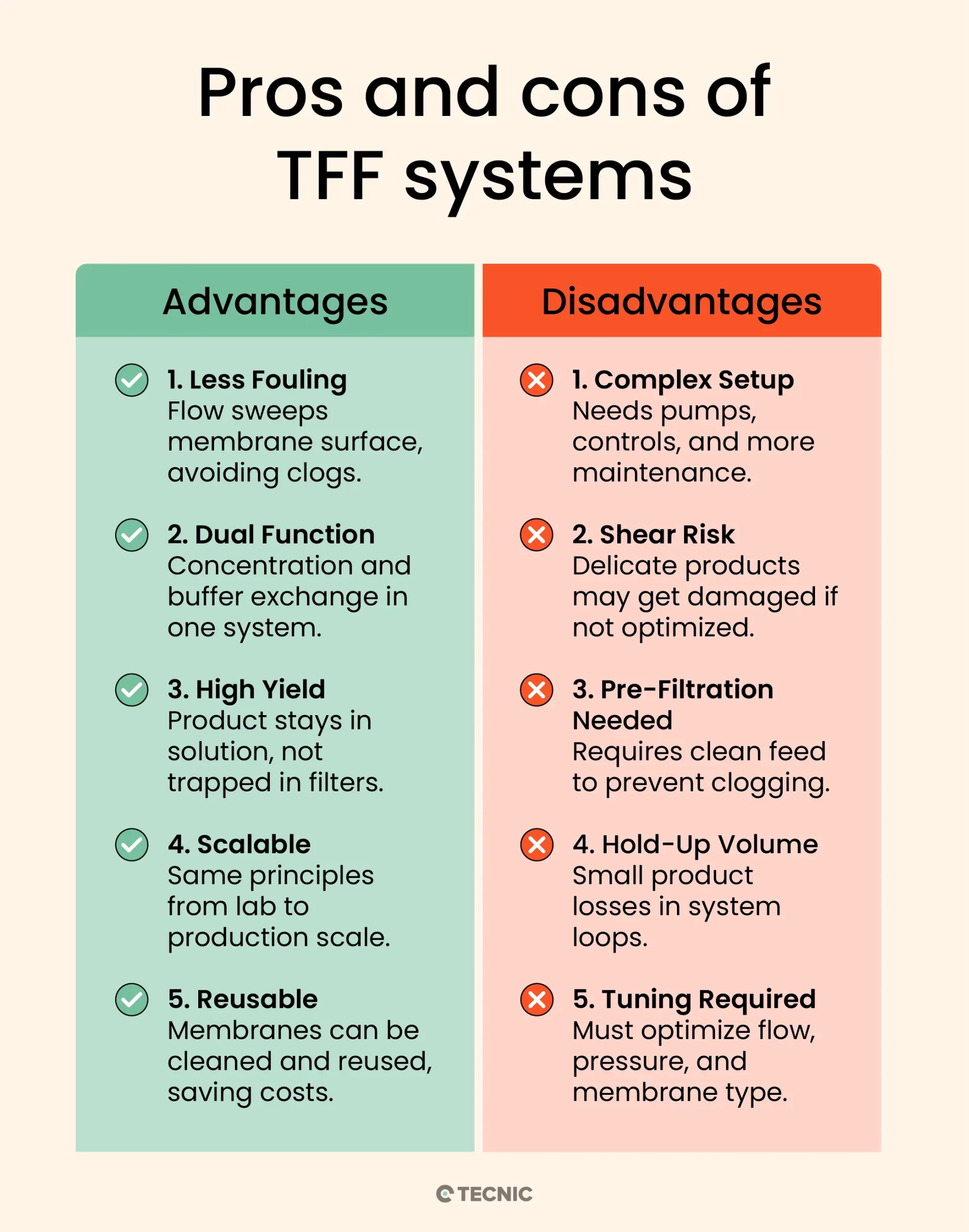
What are the key advantages of tangential flow filtration?
Reduced Fouling: Because of the tangential flow design, TFF greatly reduces filter clogging. The continuous sweeping action of fluid across the membrane prevents the buildup of a thick filter cake, which extends membrane life and maintains higher flow rates.
Process Versatility (Concentration & Diafiltration): TFF allows you to concentrate a product and also perform diafiltration (buffer exchange) in the same system, even simultaneously if desired. This is very useful in bioprocess workflows, for example, concentrating a protein and then washing out impurities with buffer in one integrated process.
High Product Yield: TFF is gentle on many biomolecules. The ability to recirculate the retentate means you don’t lose product in a discarded filter cake; instead, the valuable molecules remain in solution. Both the retentate and permeate can be recovered as needed, and membranes can often be rinsed to recover additional product. This results in high yield and efficient product recovery.
Scalability: Parameters in TFF (like cross-flow velocity and transmembrane pressure) can be kept consistent from lab scale to production scale, making scale-up more straightforward. Small TFF setups (a few milliliters) operate on the same principles as large manufacturing systems (hundreds of liters), so processes developed at bench scale can be scaled to industrial volumes with predictable performance.
Reuse and Cost Efficiency: Many TFF membranes can be cleaned (Clean-in-Place, CIP) and reused for multiple batches. While the upfront cost of a TFF system is higher than single-use filters, the ability to reuse membranes and handle large volumes can reduce cost per volume processed in the long run. Additionally, modern TFF systems are often automated, improving consistency and reducing labor.
What are the disadvantages of tangential flow filtration?
Higher Equipment Complexity: A TFF setup is more complex than a simple filter unit. It requires pumps, pressure controls, and often a recirculation tank. This means more instrumentation and maintenance. For very small-scale needs, a simple syringe filter or normal flow filter might be more convenient.
Shear Stress on Product: The cross-flow and pumping can expose the product to shear forces. Shear-sensitive materials (e.g. certain enzymes, cell therapies, or viruses with fragile envelopes) could be damaged if the TFF is not configured gently. While hollow fiber modules mitigate this, flat-sheet cassettes can be less gentle on the product. Careful control of flow rates can usually address this, but it’s a consideration.
Needs Pre-Filtration for Particulates: If the feed stream has a lot of large particulates or is very viscous, TFF can still foul or experience pressure drop issues. For example, cell culture harvest might need a pre-filter (like a depth filter) to remove cell clumps before TFF ultrafiltration. TFF membranes have low tolerance for high solids loads, they handle some suspended solids, but excessive debris will eventually clog the flow channels.
Product Hold-Up Volume: The recirculation loop in TFF means some minimum volume is required to keep the system primed (especially for hollow fiber modules which have internal volume). This can result in a bit of product being unrecoverable in the system at the end (hold-up volume). For very high-value products at small scale, this loss might be critical and other methods might be considered.
Operational Optimization: TFF has multiple parameters to optimize, flow rate, pressure, membrane choice, etc. Determining the optimal conditions can take some development work. In contrast, a single-use normal flow filter either works or clogs, it’s simpler to troubleshoot. With TFF, if performance is suboptimal, operators may need to adjust conditions (e.g. increase cross-flow velocity or lower TMP) to improve flux or yield. This learning curve is a minor drawback in using TFF technology.
What are the typical applications of TFF?
Tangential flow filtration is used across a broad range of applications in biopharma, biotechnology, and even food and environmental industries. In bioprocessing, TFF is essentially a go-to method for any step that involves concentrating a product, exchanging buffers, or clarifying solutions by size. Some typical applications include:
Virus purification and concentration: TFF is commonly used to concentrate viral particles (for vaccines or gene therapy vectors) and to separate viruses from smaller impurities. For example, virus-containing harvest fluid can be tangentially filtered using an ultrafiltration membrane that retains the virus (which might be ~100 nm in size) while allowing media, cell debris, and small contaminants to pass. Virus filtration by TFF is gentler than high-speed centrifugation and can be done at scale to yield a high titer of viral product.
Exosome isolation: Exosomes are nano-sized vesicles often purified from cell culture media or body fluids for research or therapeutic use. TFF (usually with a hollow fiber module) is an effective way to isolate and concentrate exosomes. The tangential flow allows separation of exosomes (which are typically ~50–150 nm) from both larger vesicles/cells (retained) and smaller proteins or solvents (which pass through).
Protein concentration and buffer exchange: Perhaps the most classic use of TFF is in ultrafiltration/diafiltration (UF/DF) of proteins such as monoclonal antibodies, enzymes, or other biologic drugs. After initial purification steps, proteins are often in a large volume of dilute solution. TFF can concentrate the protein to the desired level (ultrafiltration) and simultaneously or subsequently exchange the buffer (diafiltration) to put the protein into the formulation buffer required for the final product. This is routinely done in antibody manufacturing, for example, to concentrate a drug substance and remove solvents or salts.
Cell harvesting and clarification: TFF with microfiltration membranes is used to harvest cells or clarify cell lysates. In a cell harvest, a microfiltration TFF system can separate cells from their culture media, cells are retained in the retentate while the clarified media (permeate) passes through. This is useful in perfusion bioreactors and fermentation processes where cells need to be continuously removed or collected. Similarly, after cell lysis (breaking cells to release proteins), TFF can separate cell debris from the target protein solution (this is called lysate clarification).
Fractionation of biomolecules: TFF can be used to fractionate mixtures by size. For instance, you might run a TFF where the membrane’s cutoff is between the size of two proteins, one protein goes to permeate, the larger one is retained. This kind of size-based separation (ultrafiltration as an alternative to size-exclusion chromatography in some cases) is an application for certain processes.
Other uses: Tangential flow systems are also used in gene therapy (processing plasmid DNA and viral vectors), cell therapy (washing and concentrating cells under gentle conditions), vaccines (concentrating antigens or virus-like particles), blood plasma processing, and even in industries like food and beverage (e.g., clarifying juices or brewing). The pharmaceutical industry in particular relies on TFF for many downstream purification steps across a variety of products.
In summary, whenever a process calls for separating or concentrating biological material by size while preserving functionality, tangential flow filtration is a top choice. From lab scale (a few milliliters of enzyme solution) to manufacturing scale (hundreds of liters of vaccine broth), TFF systems are employed to achieve these goals efficiently
What is the difference between TFF and cross flow filtration?
There is no fundamental difference, tangential flow filtration is the same as cross flow filtration. The terms are used interchangeably in industry. “Tangential” and “cross” both describe the fluid flow being parallel to the membrane surface. In fact, TFF is often defined as TFF “also known as crossflow filtration.” Both refer to the exact same filtration principle.
To avoid confusion:
TFF (Tangential Flow Filtration) is the term more commonly used in biopharmaceutical processes and literature.
Cross Flow Filtration (CFF) is a broader term that may be used in various contexts (including water treatment, etc.) but it means the same concept.
If you encounter “cross-flow ultrafiltration” in a text, it is describing a TFF ultrafiltration process. In many references (and even product names) you’ll see TFF and crossflow used together (e.g., a “crossflow TFF system”). So, the “difference” is just in name. Both involve flowing the liquid tangentially along the membrane to prevent fouling, as opposed to normal flow (dead-end) filtration.
Bottom line: TFF = cross-flow filtration. There’s no operational difference, if you understand TFF, you understand cross flow filtration. (For completeness: You might also hear “crossflow TFF” just emphasizing the tangential method, but again, it’s the same thing.)
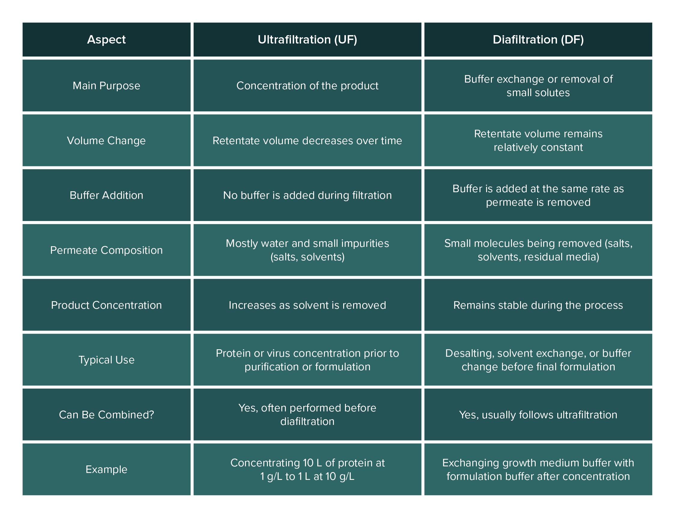
What is the difference between ultrafiltration and diafiltration?
Tangential flow filtration can be operated mainly in two modes: ultrafiltration (UF) and diafiltration (DF). Often, a single TFF process will involve both steps sequentially. Here’s how they differ:
Ultrafiltration (Concentration): Ultrafiltration refers to using TFF to concentrate a solution. In ultrafiltration mode, you run the TFF system to remove a portion of the solvent (permeate) while retaining the solute of interest in the retentate. The volume of the retentate decreases over time, and the target product becomes more concentrated. For example, starting with 10 liters of a protein at 1 g/L, ultrafiltration could concentrate it to 1 liter at 10 g/L by removing 9 liters of water through the membrane. During UF, you typically do not add any new buffer to the feed; you simply let the volume reduce. Ultrafiltration is all about retaining the big molecules and throwing away water and small impurities to achieve a higher concentration of the product.
Diafiltration (Buffer Exchange): Diafiltration is a process of washing away small molecules (like salts or solvents) and replacing the solution buffer, while keeping the volume (and product concentration) relatively constant. In diafiltration mode, fresh buffer or water is added to the retentate at the same rate that permeate is removed. This way, although you continue to filter out small solutes, the volume in the retentate tank doesn’t drastically drop (because you’re replenishing it). Diafiltration is often done after an ultrafiltration step, for instance, once the protein is concentrated, you might add a fresh buffer and continue filtering to flush out salts or exchange the buffer (maybe the protein was in a growth medium and you want it in a formulation buffer). The key point is that diafiltration is about exchange rather than concentration. Over the course of diafiltration, the undesirable small molecules are washed through the membrane with the outgoing permeate, and are replaced by the new buffer being added. By the end of diafiltration, the product remains at roughly the same concentration, but the solution it’s in has been changed (desalted or moved into a new buffer).
In practical terms, ultrafiltration and diafiltration often go hand-in-hand. Protocols commonly use “UF/DF” systems, meaning they first ultrafilter (UF) to concentrate, then diafilter (DF) to exchange buffer or further purify. Some modern systems even allow single-pass diafiltration, where buffer is continuously added so that concentration and diafiltration happen simultaneously in one pass. But conceptually, remember the difference: ultrafiltration = concentration (volume reduction), diafiltration = buffer exchange (washing while maintaining volume).
How to select the right tangential flow filtration equipment for your needs?
Selecting the appropriate TFF system and membrane for your application is crucial to achieving good results. Here are some considerations and tips to guide your selection:
1. Define Your Filtration Goal: Start by identifying what you need to accomplish. Is it concentration of a product, diafiltration for buffer exchange, or clarification of a feed stream? Your goal influences the membrane cutoff and format. For example, to concentrate a protein ~50 kDa in size, you might choose a 30 kDa ultrafiltration membrane. For clarifying cell soup, a 0.2 µm microfiltration membrane is needed.
2. Know Your Product and Its Sensitivity: Consider the nature of the product being filtered. Shear-sensitive or delicate molecules (certain enzymes, viral vectors, live cells) will benefit from a gentler TFF setup, here a hollow fiber module is often preferable due to its lower shear environment. If your product is robust (e.g., a stable antibody protein or a hardy virus), a flat-sheet cassette with higher flux might be a great choice. Also, if the product is prone to fouling the membrane (for example, if it’s sticky or tends to aggregate), you might opt for membrane materials like regenerated cellulose which have lower non-specific binding.
3. Consider Feed Volume and Scale: The volume of material you need to process is a major factor. For small volumes (a few milliliters to liters), you might use small TFF capsules or cartridges that integrate a membrane (some manufacturers offer tiny flat-sheet cassettes or syringe-size hollow fiber units). For large volumes (dozens to thousands of liters), larger cassette stacks or industrial hollow fiber skids are available. Generally, flat-sheet cassettes excel at large-scale processing they can be stacked to increase membrane area easily. Hollow fibers are also scalable (you can bundle multiple cartridges in parallel), but very large-scale processes in pharma often use cassettes. Make sure the system you choose can be scaled up: lab-scale TFF systems from major vendors often have similar geometry to their production-scale counterparts, which eases scale-up. If you foresee needing to scale, choose a technology that exists in the size range you’ll need later (e.g., don’t use a niche membrane format that isn’t available in GMP production size).
4. Feed Characteristics – Solids and Viscosity: If your feed is viscous or contains a lot of particulates, you might lean towards certain configurations. Hollow fibers generally handle slightly more particulate matter because you can perform backflushing and they have somewhat larger flow channels, but they still can clog if overloaded. Flat cassettes have narrow channels and can foul quickly with high solids. In some cases (like very high solids or extreme pH), ceramic membranes might be considered since they are very robust, but those are used mostly in niche applications. For most biotech uses, if feed is very dirty, a pre-filter step is recommended regardless of TFF type. If viscosity is high, you’ll need a strong pump and perhaps prefer a format that can tolerate higher pressures (cassettes can often operate at higher pressures than very small hollow fiber lumens, but this varies).
5. Membrane Pore Size (MWCO): Choose a molecular weight cutoff that will retain your target product while letting unwanted components through. A rule of thumb is to pick a cutoff that is 2-3 times smaller than the molecular size of your product if you want to ensure high retention. For instance, to retain a 100 kDa protein, a 50 kDa MWCO membrane might be used to ensure it doesn’t leak. If doing diafiltration, ensure the cutoff will also remove the small molecules you aim to remove (salt, etc., are just a few Daltons, so any UF membrane will remove those). For virus work (viruses are very large relative to proteins), often a membrane rated by micron size (e.g., 0.05 µm) could be chosen.
6. Material Compatibility and Reuse: Consider what cleaning or sterilization is needed. If you plan to reuse the membranes, ensure they are compatible with your cleaning agents (e.g., NaOH, acids) and can be sanitized. Some membranes (like certain polyethersulfone cassettes) can be re-used many times if cared for, whereas some single-use hollow fiber modules are intended for one-time use only. If you need single-use TFF (to avoid cleaning validation), there are capsule TFF modules on the market, those might limit size but are very convenient.
7. System Controls and Instrumentation: Simpler needs (small scale, non-critical operation) might be met with a basic lab TFF setup (manual valves and a pump). More advanced uses (especially in manufacturing) often require automated TFF systems with sensors for pressure, weight scales for permeate collection, UV monitors for product concentration, etc. When selecting equipment, ensure the system has the control capabilities you need. For example, if you need to precisely control diafiltration volume, a system with an automated pump to add buffer and a load cell to monitor volume is extremely helpful.
8. Consult Application Data: It’s often useful to look at vendor application notes or case studies for similar processes. For instance, if you’re filtering exosomes, you might find that many groups successfully use a certain hollow fiber module type for that purpose, that’s a strong hint for what to choose. Vendors usually provide guidance on cassette vs. hollow fiber for given applications.
9. Economic and Practical Considerations: Factor in cost and infrastructure. Cassettes require holders (extra cost) and typically have higher upfront membrane cost, but they might last longer and handle scale better. Hollow fiber cartridges may be cheaper per module and easier to swap in and out. If you need to frequently change membranes or have a disposable setup, hollow fibers or small capsule cassettes might be more practical. Also consider lead times, some membrane types might have longer delivery times if they’re specialty.
In summary, selecting a TFF system is about matching the module type (cassette vs hollow fiber) and membrane properties to your product’s needs and process scale. If you need gentle handling and convenience, hollow fiber TFF could be the best fit. If you need high throughput and are working with robust biomolecules, a cassette-based TFF system might be optimal. Always consider your product’s size and sensitivity, the volume you will process, and how you plan to integrate the TFF step in your overall workflow. When in doubt, perform small-scale trials with a few membrane types, this can inform your decision before committing to the full-scale system.
Conclusion
Tangential flow filtration (TFF) is more than just a method for separating fluids, it's a core enabling technology in biotechnology, biopharma, and life sciences. Its ability to process delicate biomolecules efficiently, concentrate valuable products, and perform buffer exchange makes it indispensable from research labs to commercial manufacturing.
Whether you're purifying exosomes, concentrating therapeutic proteins, harvesting cells, or preparing viral vectors for gene therapy, understanding how TFF systems work, and choosing the right membrane and module, can dramatically improve yield, reproducibility, and product quality.
Compared to traditional normal flow filtration, TFF offers lower fouling, higher throughput, and greater scalability. Choosing between flat-sheet cassettes and hollow fiber modules, selecting the appropriate membrane pore size, and configuring the system to suit the sensitivity and scale of your process are critical steps in successful implementation.
As demand for biologics and cell-based therapies continues to grow, mastering tangential flow filtration is essential for anyone working in biotech or biopharma. This guide has aimed to answer your most pressing questions and provide a clear starting point for exploring, selecting, and optimizing TFF systems for your specific needs.
Frequently Asked Questions (FAQ)
TFF is a membrane-based filtration method where liquid flows tangentially across the membrane, allowing smaller molecules to pass while retaining larger ones.
Normal flow forces liquid directly through the membrane, often clogging it, while TFF flows parallel to the membrane, reducing fouling and allowing continuous filtration.
A TFF system uses a pump to circulate fluid across a membrane; smaller particles pass through (permeate), and larger molecules are retained (retentate) and recirculated.
TFF is used for protein concentration, virus purification, exosome isolation, buffer exchange, and cell harvesting in biotech and pharma processes.
Ultrafiltration concentrates the product by removing solvent; diafiltration washes out small molecules while maintaining volume by adding buffer.
References
van Reis, R., & Zydney, A. (2007). Membrane separations in biotechnology. Current Opinion in Biotechnology, 18(3), 208–211.
Nguyen TT, Bui XT, Luu VP, Nguyen PD, Guo W, Ngo HH. Removal of antibiotics in sponge membrane bioreactors treating hospital wastewater: Comparison between hollow fiber and flat sheet membrane systems. Bioresour Technol. 2017 Sep;240:42-49.
Oetomo, B., Luo, L., Qu, Y., Discepola, M., Kentish, S. E., & Gras, S. L. (2025). Controlling tangential flow filtration in biomanufacturing processes via machine learning: A literature review. Digital Chemical Engineering, 14, 100211.
Benítez, F. J., Acero, J. L., Leal, A. I., & González, M. (2009). The use of ultrafiltration and nanofiltration membranes for the purification of cork processing wastewater. Journal of Hazardous Materials, 162(2–3), 1438–1445
McCarney, L., Ravichandran, A. G., Tansey, S., Dango, M., & Marchand, N. (2025). A blueprint for TFF format selection: Hollow fibers and flat sheets for ultrafiltration of AAV. Separation and Purification Technology, 370, 133064